
Subscribe to Our Youtube Channel
Related Manuals for BUSCH R5 RA 1000


Summary of Contents for BUSCH R5 RA 1000
- Page 1 Oil-Lubricated Rotary Vane Vacuum Pumps RA 1000 B, RA 1600 B RC 1000 B, RC 1600 B Instruction Manual 0870569784 | -0008_en-US | Original instructions 8/13/2022...
-
Page 2: Table Of Contents
Table of Contents Table of Contents Safety..................................Product Description ............................. Operating Principle ............................. Intended Use ............................... Start Controls ............................... Standard Accessories............................2.4.1 Temperature Switch "Gas"........................2.4.2 Level Switch ............................2.4.3 Temperature Switch "Oil"........................Optional Accessories............................2.5.1 Gas Ballast Valve ........................... 2.5.2 Inlet Filter ............................... - Page 3 Table of Contents Overhaul................................Decommissioning..............................10.1 Dismantling and Disposal ..........................Spare Parts................................Troubleshooting..............................Technical Data ..............................Oil ................................... EU Declaration of Conformity..........................UK Declaration of Conformity ..........................Instruction Manual R5 RA RC 1000-1600 B_EN_en 3 | 44...
-
Page 4: Safety
Safety Prior to handling the machine, this instruction manual should be read and understood. If anything needs to be clarified, please contact your Busch representative. Read this manual carefully before use and keep for future reference. This instruction manual remains valid as long as the customer does not change anything on the product. -
Page 5: Product Description
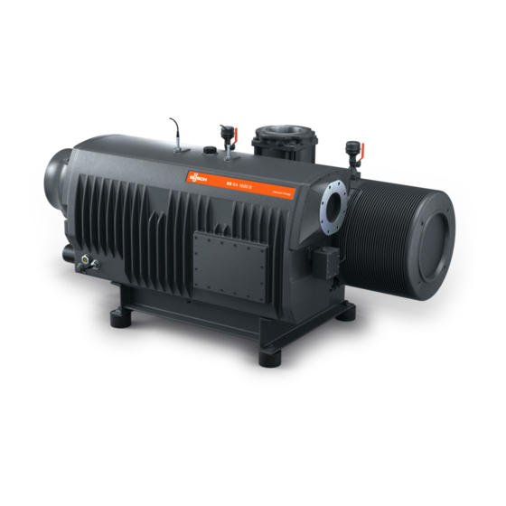
Product Description | 2 Product Description TS 1 TS 2 GB 1 GB 2 OUT 1 TS 3 OUT 2 Description Suction connection (Inlet) Discharge connection (Outlet) Air-oil heat exchanger Directional arrow Eye bolt Exhaust filter Filter material Float valve (on RA version only) Gas ballast valve Level switch Motor terminal box... -
Page 6: Operating Principle
Busch. The machine is intended for the placement in a non-potentially explosive environment. The machine is designed for indoor installation, in case of outdoor installation, ask your Busch rep- resentative in order to take specific precautions. -
Page 7: Standard Accessories
Product Description | 2 Standard Accessories 2.4.1 Temperature Switch "Gas" The temperature switch “Gas” monitors the gas temperature of the machine. The machine must be stopped when the gas reaches 110 °C. 2.4.2 Level Switch The level switch monitors the oil level. The machine must be stopped when the oil level is too low. -
Page 8: Variable Speed Drive
The machine can optionally be equipped with a Variable Speed Drive (VSD). A variable speed drive in- creases the pumping speed of the machine and saves energy. For more information contact your Busch representative. 8 | 44 Instruction Manual R5 RA RC 1000-1600 B_EN_en... -
Page 9: Transport
Transport | 3 Transport WARNING Suspended load. Risk of severe injury! ● Do not walk, stand or work under suspended loads. WARNING Lifting the machine using the motor eye bolt. Risk of severe injury! ● Do not lift the machine using the eye bolt fitted to the motor. Only lift the machine as shown. NOTICE In case the machine is already filled with oil. -
Page 10: Storage
4 | Storage Storage ● Seal all apertures with adhesive tape or reuse provided caps. Version with water-oil heat exchanger: ● Make sure that the cooling water has been completely drained, see Decommissioning [➔ 34]. If the machine is equipped with a variable speed drive: NOTICE Long storage time. -
Page 11: Installation
Installation | 5 Installation Installation Conditions NOTICE Use of the machine outside of the permitted installation conditions. Risk of premature failure! Loss of efficiency! ● Take care that the installation conditions are fully complied with. ~50 cm ~100 cm ~100 cm ~50 cm ●... -
Page 12: Connecting Lines / Pipes
Depending on the specific configuration ordered, other connection dimensions may apply. If the machine is used as part of a vacuum system: ● Busch recommends the installation of an isolation valve in order to prevent the oil from flow- ing back to the vacuum system. -
Page 13: Discharge Connection
Installation | 5 5.2.2 Discharge Connection CAUTION The discharge gas contains small quantities of oil. Risk to health! If air is discharged into rooms where persons are present: ● Make sure that sufficient ventilation is provided. NOTICE Discharge gas flow obstructed. Risk of damage to the machine! ●... -
Page 14: Cooling Water Connection (Optional)
5 | Installation 5.2.3 Cooling Water Connection (Optional) Description Water-oil heat exchanger without inlet Water-oil heat exchanger with inlet ac- accessories cessories Description Cooling water inlet Pressure switch Cooling water outlet Water bypass valve Water-oil heat exchanger Water filter Thermostatic valve Solenoid valve The thermostatic valve (TV) is used to control the water flow in order to keep a stable vacuum pump temperature. -
Page 15: Filling Oil
Risk of premature failure! Loss of efficiency! ● Only use an oil type which has previously been approved and recommended by Busch. For oil type and oil capacity see Technical Data [➔ 38] and Oil [➔ 39]. Instruction Manual R5 RA RC 1000-1600 B_EN_en... -
Page 16: Fitting The Coupling
5 | Installation Fitting the Coupling NOTE Radial screw. For trouble-free operation, use thread locking glue to secure the radial screw. Description Coupling hub (machine side) Coupling sleeve Coupling hub (motor side) Radial screw / max. admissible torque: 17Nm 16 | 44 Instruction Manual R5 RA RC 1000-1600 B_EN_en... - Page 17 Installation | 5 Machine type Coupling size Value “E” (mm) Value “L” (mm) BoWex ® I-80 RA/RC 1000 B POLY PKZ 17 POLY PKZ 20 BoWex ® I-80 RA/RC 1600 B POLY PKZ 20 In case of a machine delivery without motor: ●...
-
Page 18: Electrical Connection
● Make sure that the motor of the machine will not be affected by electric or electro- magnetic dis- turbance from the mains, if necessary seek advice from Busch. ● Make sure that the EMC of the machine is compliant with the requirements of your supply net- work system, if necessary provide further interference suppression (EMC of the machine, see EU Declaration of Conformity [➔ 40] or UK Declaration of Conformity [➔ 41]). -
Page 19: Machine Delivered With A Control Box (Option)
● If the machine is equipped with a power connector, install a residual current protective device to protect persons in case of isolation default. ● Busch recommends installing a type B residual protective device suitable for the electrical in- stallation. -
Page 20: Machine Delivered With A Variable Speed Drive (Option)
● If the machine is equipped with a power connector, install a residual current protective device to protect persons in case of isolation default. ● Busch recommends installing a type B residual protective device suitable for the electrical in- stallation. -
Page 21: Wiring Diagram Three-Phase Motor
Electrical Connection | 6 NOTICE Incorrect connection. Risk of damage to the variable speed drive! ● The wiring diagrams given below are typical. Check the connection instructions/diagrams. Wiring Diagram Three-Phase Motor NOTICE Incorrect direction of rotation. Risk of damage to the machine! ●... -
Page 22: Electrical Connection Of The Monitoring Devices
(middle voltage): Electrical Connection of the Monitoring Devices NOTE In order to prevent potential nuisance alarms, Busch recommends that the control system is configured with a time delay of at least 20 seconds. 6.5.1 Wiring Diagram Temperature Switch "Gas"... -
Page 23: Wiring Diagram Level Switch
Electrical Connection | 6 6.5.3 Wiring Diagram Level Switch Part no.: 0652 567 576 Connector: M12x1, 4-pin Electrical data: U = 10 – 30 V DC I consumption : <15 mA I output max : 150 mA Switch point: 1 = Brown: Supply +24V DC Pin 1 = low level 3 = Blue: Supply 0V DC 4 = Black: Signal low level... -
Page 24: Wiring Diagram Pressure Switch Of Water-Oil Heat Exchanger (Optional)
6 | Electrical Connection 6.5.8 Wiring Diagram Pressure Switch of Water-oil Heat Exchanger (Optional) Part no.: 0653 000 002 Electrical data: P > U = 230 VAC ; I = 1 A U = 24 … 100 VDC ; I = 0.5 … 2 A Contact: Normally open Switch point: = 2 bar (relative) ►... -
Page 25: Commissioning
Conveying Condensable Vapors Water vapor within the gas flow is tolerated within certain limits. The conveyance of other vapors shall be agreed upon with Busch. If condensable vapors are to be conveyed: START ● Close the isolation valve* and open the gas ballast valve** (GB) ●... - Page 26 7 | Commissioning ● Wait 30 minutes ● Open the isolation valve* and perform the process ● Close the isolation valve* ● Wait 30 minutes ● Close the gas ballast valve** (GB) * not included in the scope of delivery ** may be considered as optional on certain products 26 | 44 Instruction Manual R5 RA RC 1000-1600 B_EN_en...
-
Page 27: Maintenance
Risk of injuries! Risk of premature failure and loss of efficiency! ● Maintenance work must only be executed by qualified personnel. ● Respect the maintenance intervals or ask your Busch representative for service. NOTICE Using inappropriate cleaners. Risk of removing safety stickers and protective paint! ●... -
Page 28: Maintenance Schedule
8 | Maintenance If the machine is equipped with a variable speed drive: DANGER Maintenance work without disconnecting the variable speed drive. Risk of electrical shock. ● Disconnect and isolate the variable speed drive before attempting any work on it. High voltages are present at the terminals and within the variable speed drive for up to 10 min- utes after disconnection of the electrical supply. -
Page 29: Oil Level Inspection
● Contact Busch for an inspection. Every 5 years If required, overhaul the machine. * Service interval for synthetic oil, shorten the interval when using mineral oil, contact Busch Service Oil Level Inspection ● Shut down the machine. ● When the machine is stopped, wait 1 minute before checking the oil level. - Page 30 Description Oil filter wrench 2x oil filter (OF) - Part No. 0531 000 005 (Busch genuine spare part) For oil type and oil capacity see Technical Data [➔ 38] and Oil [➔ 39]. 30 | 44 Instruction Manual R5 RA RC 1000-1600 B_EN_en...
-
Page 31: Exhaust Filter Change
Description 16x (2x8) exhaust filter (EF) - Part No. Filter material (FM) - 1x Part No. 0537 0532 140 160 (Busch genuine spare 000 042 + 1x Part No. 0537 000 043 part) 2x flat gasket - Part No. 0480 000 131 6 mm hex key / max. -
Page 32: Air Heat Exchanger Cleaning
8 | Maintenance Air Heat Exchanger Cleaning ● Use compressed air and wear protective eyewear and mask. 32 | 44 Instruction Manual R5 RA RC 1000-1600 B_EN_en... -
Page 33: Overhaul
● Decontaminate the machine as much as possible and state the contamination status in a ‘Dec- laration of Contamination’. Busch will only accept machines that come with a completely filled in and legally binding signed ‘Declaration of Contamination’ (form downloadable from www.buschvacuum.com). -
Page 34: Decommissioning
10 | Decommissioning Decommissioning DANGER Live wires. Risk of electrical shock. ● Electrical installation work must only be executed by qualified personnel. CAUTION Hot surface. Risk of burns! ● Prior to any action requiring touching the machine, let the machine cool down first. ●... -
Page 35: Spare Parts
Use of non-Busch genuine spare parts. Risk of premature failure! Loss of efficiency! ● The exclusive use of Busch genuine spare parts and consumables is recommended for the correct functioning of the machine and to validate the warranty. Spare parts kit Description Part no. -
Page 36: Troubleshooting
12 | Troubleshooting Troubleshooting DANGER Live wires. Risk of electrical shock. ● Electrical installation work must only be executed by qualified personnel. DANGER Live wires. Carry out any work on the variable speed drive and motor. Risk of electrical shock! ●... - Page 37 ● Clean the filter of the gas ballast valve (GB). ● Modify the operational mode (see Conveying Con- densable Vapors [➔ 25]). For the solution of problems not mentioned in the troubleshooting chart contact your Busch representative. Instruction Manual R5 RA RC 1000-1600 B_EN_en 37 | 44...
-
Page 38: Technical Data
13 | Technical Data Technical Data RA 1000 B RA 1600 B RC 1000 B RC 1600 B Nominal pumping speed m³/h 1000 / 1200 1600 / 1800 (50Hz / 60Hz) Ultimate pressure hPa (mbar) abs. RA version: 0.3 ... 0.5 ► see nameplate (NP) (without gas ballast valve) RC version: 20.0 Ultimate pressure... -
Page 39: Oil
Oil temperature [°C] In case of unfavorable ambient temperature, other oil viscosities may be used. Please consult your Busch representative for more details. To know which oil has been filled in the machine, please refer to the nameplate (NP). Instruction Manual R5 RA RC 1000-1600 B_EN_en... -
Page 40: Eu Declaration Of Conformity
EU Declaration of Conformity This Declaration of Conformity and the CE-markings affixed to the nameplate are valid for the machine within the Busch scope of delivery. This Decla- ration of Conformity is issued under the sole responsibility of the manufacturer. -
Page 41: Uk Declaration Of Conformity
UK Declaration of Conformity This Declaration of Conformity and the UKCA-markings affixed to the nameplate are valid for the machine within the Busch scope of delivery. This Dec- laration of Conformity is issued under the sole responsibility of the manufacturer. - Page 42 Notes 42 | 44 Instruction Manual R5 RA RC 1000-1600 B_EN_en...
- Page 43 Instruction Manual R5 RA RC 1000-1600 B_EN_en 43 | 44...
- Page 44 With a network of over 60 companies in more than 40 countries and agencies worldwide, Busch has a global presence. In every country, highly competent local personnel delivers custom-tailored support backed by a global network of expertise. Wherever you are.
Need help?
Do you have a question about the R5 RA 1000 and is the answer not in the manual?
Questions and answers