BUSCH R5 Instruction Manual
Oil-lubricated rotary vane vacuum pumps
Hide thumbs
Also See for R5:
- User manual ,
- Instruction manual (56 pages) ,
- Instructions manual (52 pages)

Related Manuals for BUSCH R5


Summary of Contents for BUSCH R5
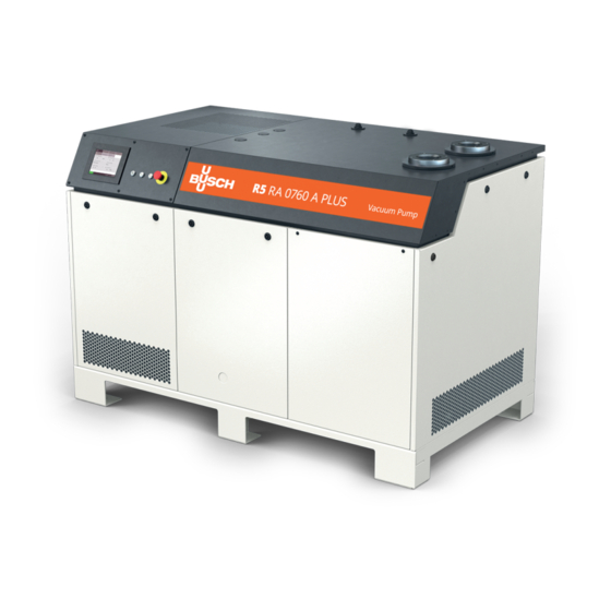
- Page 1 Instruction Manual Oil-Lubricated Rotary Vane Vacuum Pumps RA 0760 A PLUS Ateliers Busch S.A. Zone industrielle, 2906 Chevenez Switzerland 0870211676/-0004_en / Original instructions / Modifications reserved 10/02/2021...
-
Page 2: Table Of Contents
Table of Contents Table of Contents 1 Safety ............................4 2 Product Description ........................5 2.1 Operating Principle ......................7 2.2 Application........................7 2.3 Standard Features ......................7 2.3.1 User Interface ......................7 2.3.2 Acoustic Cabinet ....................7 2.3.3 Control Unit ......................7 2.3.4 Monitoring Devices .................... - Page 3 Table of Contents 7.2 Operating Mode ......................34 7.2.1 Speed Control ....................... 34 7.2.2 Pressure Control ....................35 7.3 Ecomode .......................... 36 7.4 Gas Ballast Valve Control ....................37 7.5 Warm-up / Cool-down Modes..................38 7.5.1 Conveying Condensable Vapours ................39 7.6 Optional Inlet Valve Control.....................
-
Page 4: Safety
Safety Prior to handling the machine, this instruction manual should be read and understood. If anything needs to be clarified, please contact your Busch representative. Read this manual carefully before use and keep for future reference. This instruction manual remains valid as long as the customer does not change anything on the product. -
Page 5: Product Description
Product Description | 2 Product Description Acoustic cabinet Air-oil heat exchanger Alarm indicator light Cooling air inlet Cooling air outlet I/O port (D-Sub 9) Control unit Emergency stop switch User interface (human-machine) Suction connection Communication port (Modbus TCP/IP) Nameplate Discharge connection Power indicator light Power supply (cable gland) Start/Stop button... - Page 6 2 | Product Description Vacuum pump (VP) PSA1 PSA2 Exhaust filter Gas ballast valve Inlet filter Level switch (oil level) Motor (pump drive) Oil filter Oil drain plug Oil fill plug Oil separator Oil sight glass PSA1 Pressure transmitter PSA2 Pressure transmitter (inlet gas pressure) (exhaust gas pressure in the oil separator)
-
Page 7: Operating Principle
Conveying of other media leads to an increased thermal and/or mechanical load on the machine and is permissible only after a consultation with Busch. The machine is intended for the placement in a non-potentially explosive environment. The machine is designed for indoor installation, in case of outdoor installation, ask your Busch representative in order to take specific precautions. -
Page 8: Monitoring Devices
– RJ45 (Modbus) • Refer to the specific document “Pump Control Instructions, art. no.: 0870213261” for more details or contact your Busch representative. 2.3.6 Gas Ballast Valve The gas ballast valve mixes the process gas with a limited quantity of ambient air to counteract the condensation of vapour inside the machine. -
Page 9: P&Id "Piping And Instrumentation Diagram
Product Description | 2 2.5 P&ID "Piping and Instrumentation Diagram" DN80 PN6 PSA1 inlet gas MOT2 MOT1 PSA2 exhaust gas low oil level alarm (trip) exhaust gas DN80 PN6 Air-oil heat exchanger Coupling Gas ballast Inlet filter Suction connection Level switch "alarm/trip” (oil level) MOT1 Motor (pump drive) MOT2... -
Page 10: Description Of User Interface Functions
2 | Product Description 2.7 Description of User Interface Functions The display is divided into three distinct parts. Menu tabs Information panel Bottom bar 01.08.2020 - 15:00 2.7.1 Menu Overview The menu consists of four main tabs with their own sub-tabs: –... -
Page 11: Bottom Bar
Product Description | 2 2.7.2 Bottom Bar The bottom bar provides different pieces of information, in particular the machine state and warning/alarm status. Warnings and alarms Date and hour Help Machine state status 01.08.2020 - 15:00 Screen WARNING brightness RUNNING ALARM 2.7.3 Navigation When several screens are available in the information panel, dots and “PREVIOUS/... -
Page 12: Role And User
– set the remote control and monitoring parameters, refer to the specific document "Pump Control Instructions, art. no.: 0870213261". – Role 3 ► Busch Service Only authorized personnel from Busch Service have this level of access rights. NOTE In case of any questions related to the machine settings: •... -
Page 13: System Settings
Thresholds can only be changed by Busch Service “Role 3”, see the predefined factory settings in the chapter Warnings and Alarms Thresholds [► 51]. NOTE Advanced settings Advanced settings can only be changed by Busch Service “Role 3”, refer to the specific document "Pump Control Instructions, art. no.: 0870213261". 0870211676_RA0760A_PLUS_-0004_IM_en 13 / 68... -
Page 14: Machine And Software Identification
HOME OPERATIONS MODEL SETTINGS CONTACT ETHERNET Vacuum pump type Vacuum pump model R5 PLUS RA 0760 A Software HMI Software PLC Serial number CHM120400012 2.7.7 Ethernet Settings To configure the ethernet settings according to your network: • Go to “SYSTEM” > “ETHERNET”. -
Page 15: Web Visualization
Product Description | 2 SYSTEM HOME MAINTENANCE OPERATIONS SETTINGS MODEL ETHERNET CONTACT Ethernet settings Change settings Current IP address New IP address 192 . 168 . Current subnet mask New subnet mask 255 . 255 . 255 . Current gateway New gateway 192 . - Page 16 2 | Product Description • Open your web browser (full screen window) and type the IP address of the machine to monitor in the address bar, followed by: :8080/smartpump.htm. By default, the whole address to be typed in the web browser is: 192.168.0.22:8080/smartpump.htm •...
- Page 17 Product Description | 2 • The second page “Service” shows the service table of the machine and Busch service contact information. • The third page “My vacuum pump” gives general information about the machine. NOTE • Contact Busch: ð If the Ethernet port of the machine (COM) is already used for remote control / monitoring purpose.
-
Page 18: Transport
3 | Transport Transport WARNING Suspended load. Risk of severe injury! • Do not walk, stand or work under suspended loads. NOTICE In case the machine is already filled with oil. Tilting a machine that is already filled with oil can cause large quantities of oil to in- gress into the cylinder. -
Page 19: Storage
Storage | 4 As soon as the machine is placed at its final location: • Remove the reinforcement bar as it can hinder a technician when performing main- tenance tasks. • Conserve and remount it for future machine transport. 13 mm wrench Remove side cover ¼... -
Page 20: Installation
• Make sure that all provided covers, guards, hoods, etc. are mounted. If the machine is installed at an altitude greater than 1000 meters above sea level: • Contact your Busch representative, the motor should be derated or the ambient temperature limited. -
Page 21: Connecting Lines / Pipes
– DN80 PN6, EN 1092-1 If the machine is used as part of a vacuum system: • Busch recommends the installation of an isolation valve in order to prevent the oil from flowing back to the vacuum system. 5.2.2 Discharge Connection Connection size(s): –... -
Page 22: Cooling Water Connection (Optional)
5 | Installation 5.2.3 Cooling Water Connection (Optional) Water-oil heat exchanger with inlet and outlet connection Cooling fan Cooling water inlet Cooling water outlet Solenoid valve Thermostatic valve Water filter Water-oil heat exchanger The thermostatic valve (TV) is used to control the oil flow in order to keep a stable ma- chine temperature. -
Page 23: Inlet Filter Condition Monitoring Kit
Installation | 5 Hardness mg/l (ppm) < 90 Properties Clean & clear PH value 7 ... 8 Particle size µm < 200 Chloride mg/l < 100 Electrical conductivity µS/cm ≤ 100 Free chloride mg/l < 0.3 Materials in contact with the cooling water Stainless steel, copper and cast iron NOTE Water hardness unit conversion. -
Page 24: External Inlet Pressure Sensor
5 | Installation 5.2.5 External Inlet Pressure Sensor An external inlet pressure sensor can be connected to the Control Unit. To control the machine with an external sensor: – Mechanically fit the Pressure Sensor at the desired location upstream of the vacuum pump inlet (on a vacuum vessel or in the vacuum chamber for instance). -
Page 25: Filling Oil
(mineral or synthetic) written on the nameplate (NP). In case of oil type change: • Contact your Busch representative to adapt the thresholds and service intervals ac- cordingly. For oil type and oil capacity see Technical Data [► 66] and Oil [► 66]. -
Page 26: Fitting The Coupling
5 | Installation 5.4 Fitting the Coupling Coupling hub (machine side) Coupling sleeve Coupling hub (motor side) Radial screw Max. admissible torque: 17 Nm Coupling size Value “E” (mm) Value “L” (mm) ® BoWex M-65 In case of a machine delivery without motor: •... -
Page 27: Electrical Connection
• Provide an overload protection according to EN 60204-1 for the machine. • Busch recommends installing a C-curve circuit breaker. • Make sure that the variable-frequency drive, the motor and other electrical devices will not be affected by electric or electromagnetic disturbance from the mains; if ne- cessary seek advice from Busch. -
Page 28: Wiring Diagram Control Unit
5 | Installation 5.5.1 Wiring Diagram Control Unit Internal view of the control unit: PLC1 DO1DI1 AI1 on EMC filter Filter L1 L2 L3 Box fan Power input Customer power supply: Wire gauge according to EN 60204-1 Power supply 3L+PE 380-440V +/-5% 50/60Hz Lockable disconnect switch Overload protection... -
Page 29: Commissioning
Commissioning | 6 • Make sure that the air flow blows in the right direction according to the following il- lustration. Air flow (blowing) Rotation direction of the fan If the rotation must be changed: • Switch any two of the phase wires. Commissioning 6.1 Prerequisites Before Use •... -
Page 30: Start Up
– Optional Inlet Valve Control [► 40], – Optional Vacuum Booster Control [► 42]. Do not hesitate to contact Busch to get any further information about the configuration of your machine. • Click on the “Help” icon in the bottom bar to get the contact information of your Busch representative, see Bottom Bar [► 11]. -
Page 31: In Operation
In Operation | 7 NOTE Control mode “Remote/Auto“. The machine cannot be started manually if the control mode is set to “Remote/Auto”. In Operation CAUTION During operation the surface of the suction and exhaust connections may reach temper- atures of more than 70°C. Risk of burns! •... -
Page 32: Local/Manual
7 | In Operation 7.1.1 Local/Manual Configured by default, this mode allows to control manually the machine directly from the user interface (HMI). Control mode Manual Auto Local Start / Stop Digital speed control Remote Analog speed control Modbus control 7.1.2 Local/Auto "Week Planner"... -
Page 33: Remote/Auto
Remote Analog speed control Modbus control • Refer to the specific document “Pump Control Instructions, art. no.: 0870213261” for more details or contact your Busch representative. WARNING The machine may start without notice. Risk of severe injury! As soon as the “Remote” mode is activated: •... -
Page 34: Operating Mode
7 | In Operation 7.2 Operating Mode To access the operating mode menu: • Go to “OPERATIONS” > “MODE” • Stay on the first screen. SYSTEM MAINTENANCE HOME OPERATIONS MODE PARAMETERS WEEK PLANNER Operating mode Speed control 60 Hz Pressure control 20 mbar NEXT 7.2.1 Speed Control... -
Page 35: Pressure Control
• For smooth process pressure control, it is required to adjust the PID parameters. • Refer to the specific document “Pump Control Instructions, art. no.: 0870213261” for more details or contact your Busch representative. NOTE Display of the ultimate pressure. -
Page 36: Ecomode
7 | In Operation 7.3 Ecomode The Ecomode stops the machine when the inlet pressure has reached the preset "eco- mode pressure" within a defined time delay and will restart once the inlet pressure ex- ceeds the "restart pressure". This mode is only available for “Role 2” users, see Role and User [► 12]. To active and set the Ecomode: •... -
Page 37: Gas Ballast Valve Control
In Operation | 7 7.4 Gas Ballast Valve Control The gas ballast valve can be controlled (open/closed position) via a simple switch button. This operation is only available for “Role 2” users. To change the state of the gas ballast valve: •... -
Page 38: Warm-Up / Cool-Down Modes
7 | In Operation 7.5 Warm-up / Cool-down Modes The warm-up mode allows the machine to obtain a suitable operating temperature for the process. The cool-down mode allows the evacuation of any condensable vapours, see Conveying Condensable Vapours [► 39]. During these phases, the pump operates at maximum speed, with the gas ballast valve open, in order to warm up and evacuate a maximum of humidity. -
Page 39: Conveying Condensable Vapours
Conveying Condensable Vapours [► 39]. 7.5.1 Conveying Condensable Vapours Water vapour within the gas flow is tolerated within certain limits. The conveyance of other vapours shall be agreed upon with Busch. If condensable vapours are to be conveyed: 70° C or •... -
Page 40: Optional Inlet Valve Control
7 | In Operation 7.6 Optional Inlet Valve Control This menu allows the control and setting of the opening parameters of an isolation valve installed at the suction side of the vacuum pump (not included in the scope of delivery of the vacuum pump). - Page 41 In Operation | 7 PLUS Pump control unit Inlet Valve command line 24VDC from PLUS Pump Max 1A X1 0VDC Customer side Power line from Customer customer with relay appropriate protection Customer Inlet valve Inlet Valve Wiring Diagram NOTE The installation of an isolation valve at the vacuum pump inlet also requires the installa- tion of an external pressure sensor to control the vacuum pump, see External Inlet Pres- sure Sensor [► 24].
-
Page 42: Optional Vacuum Booster Control
7 | In Operation 7.7 Optional Vacuum Booster Control This menu allows the control and setting of the start-up parameters of a vacuum booster installed at the suction side of the vacuum pump (not included in the scope of delivery of the vacuum pump). - Page 43 Vacuum Booster Vacuum Booster Wiring Diagram NOTICE Vacuum booster compatibility. Risk of damage to the machine! • Contact Busch to check the compatibility of the vacuum booster with the vacuum pump and the recommended starting pressure. 0870211676_RA0760A_PLUS_-0004_IM_en 43 / 68...
-
Page 44: Monitoring
7 | In Operation 7.8 Monitoring 7.8.1 Operating Information This display “HOME” > “MAIN” corresponds to the principal menu and is automatically loaded when the machine is started. It displays the principal operating information. HOME MAINTENANCE SYSTEM OPERATIONS ALARM MAIN MONITORING Inlet pressure Rotation speed... -
Page 45: Operating Data
In Operation | 7 7.8.2 Operating Data This display “HOME” > “MONITORING” displays operating values, it is divided into three different screens. Screen 1 HOME OPERATIONS MAINTENANCE SYSTEM ALARM MAIN MONITORING > Gas-ballast valve Exhaust pressure Open 960 mbar Instant absorbed power Mean absorbed power 11.5 kW 10.2 kW... - Page 46 7 | In Operation Screen 2 HOME OPERATIONS MAINTENANCE SYSTEM ALARM MAIN MONITORING Oil temperature Exhaust gas temperature 82 °C Oil level Motor frequency 60 Hz PREVIOUS NEXT Oil temperature: Indicates the oil temperature, in case of a too high temperature a warning or an alarm occurs, see Dysfunction [► 51].
- Page 47 In Operation | 7 Screen 3 HOME OPERATIONS MAINTENANCE SYSTEM MAIN MONITORING ALARM Energy consumption since last reset Reset energy consumption (Press button 5s) 921 kWh Energy consumption total Motor start counter 5412 kWh Inlet filter pressure differential = 1 mbar PREVIOUS NEXT Energy consumption since last reset:...
-
Page 48: History
7 | In Operation 7.8.3 History This display “MAINTENANCE” > “HISTORY” shows the history of: – Events ► Parameter changes, function activation, etc… – Alarms ► Alarm signals from sensors – Warnings ► Warning signals from sensors – Service ► Service tasks completed It is possible to filter the type of message by selecting a specific tab. -
Page 49: Operating Curves
In Operation | 7 7.8.4 Operating Curves This display “MAINTENANCE” > “TREND” shows the trend curve of certain operating values. It offers the possibility to change the time lapse and the curve of four different operating values. MAINTENANCE SYSTEM HOME OPERATIONS HISTORY SERVICE... - Page 50 7 | In Operation If more than one curve type is selected, a matching scale appears to the right of the graph. MAINTENANCE SYSTEM HOME OPERATIONS HISTORY SERVICE TREND Power consumption Oil temperature <=> 10kW <=> 100°C Select curve -5min 08.40.24 -15min -10min...
-
Page 51: Dysfunction
In Operation | 7 7.9 Dysfunction 7.9.1 Warnings and Alarms Thresholds When the machine has reached the limit threshold of an operating value, which is pre- defined in the system, a signal is sent and visible in the bottom bar. There are two signal levels: –... -
Page 52: Warning/Alarm Acknowledgment Procedure
NOTE Threshold values are preset with the factory settings. However, depending on the applic- ation, it is possible to adjust the threshold values only after Busch approval. Threshold changes are only available for "Role 3" users. 7.9.2 Warning/Alarm Acknowledgment Procedure... -
Page 53: Stop The Machine
Maintenance | 8 7.10 Stop the Machine To stop the machine: • Press and hold the start/stop button (SSB) for at least 3 seconds. In case of emergency stop: • Push the emergency stop switch (ESS). As long as the power indicator light (PIL) is green, the machine is still powered. NOTE Control mode “Remote/Auto”. -
Page 54: Maintenance Schedule
Failing to properly maintain the machine. Risk of injuries! Risk of premature failure and loss of efficiency! • Respect the maintenance intervals or ask your Busch representative for service. 8.1 Maintenance Schedule The maintenance intervals depend very much on the individual operating conditions. The intervals given below are considered as starting values which should be shortened or ex- tended as appropriate. - Page 55 Maintenance | 8 MAINTENANCE SYSTEM HOME OPERATIONS HISTORY SERVICE TREND Next exhaust filters service Exhaust filters service interval 3993 h 4000 h Reset Last service: 00.00.0000 0 Running hour(s) Next oil service Oil service interval 3993 h 4000 h Reset Last service: 00.00.0000 0 Running hour(s)
-
Page 56: Oil Level Inspection
By default, the oil temperature thresholds (warning/alarm) and the service intervals are configured according to the oil type (mineral or synthetic) written on the nameplate (NP). In case of oil type change: • Contact your Busch representative to adapt the thresholds and service intervals ac- cordingly. 56 / 68 0870211676_RA0760A_PLUS_-0004_IM_en... - Page 57 0486 000 505 ¼ Remove central front cover Quarter turn (delivered loose) Drain pan Busch genuine spare parts 1x oil filter (OF), part no.: 0531 000 005 Unscrew the oil filter if necessary use an oil filter wrench 0870211676_RA0760A_PLUS_-0004_IM_en 57 / 68...
-
Page 58: Exhaust Filter Change
8 | Maintenance For oil type and oil capacity see Technical Data [► 66] and Oil [► 66]. Check oil level 8.4 Exhaust Filter Change 6 mm hex key Remove side cover ¼ 8x exhaust filter (EF) 58 / 68 0870211676_RA0760A_PLUS_-0004_IM_en... -
Page 59: Machine Cleaning
Maintenance | 8 6 mm hex key Max. admissible torque: 21 Nm 1x flat gasket part no.: 0480 000 131 O-ring ¼ 8.5 Machine Cleaning • Clean the cooling air inlet and outlet (CAI/CAO) with pressurised air, especially when the machine is in a dusty environment. •... -
Page 60: Inlet Filter Cartridge Change
• Decontaminate the machine as much as possible and state the contamination status in a ‘Declaration of Contamination’. Busch will only accept machines that come with a completely filled in and legally binding signed ‘Declaration of Contamination’ (form downloadable from www.buschvacuum.com). -
Page 61: Decommissioning
Use of non-Busch genuine spare parts. Risk of premature failure! Loss of efficiency! • The exclusive use of Busch genuine spare parts and consumables is recommended for the correct functioning of the machine and to validate the warranty. Spare parts kit Description Part no. -
Page 62: Troubleshooting
12 | Troubleshooting 12 Troubleshooting DANGER Carry out any work on the control unit and motor. Risk of electrical shock! • Electrical installation work must only be executed by qualified personnel. CAUTION Hot surface. Risk of burns! • Prior to any action requiring touching the machine, let the machine cool down first. NOTICE Variable-frequency drive maintenance. - Page 63 The inlet filter cartridge (IF) • Replace the inlet filter is partially clogged. cartridge (IF). Internal parts are worn or • Repair the machine (con- damaged. tact Busch). The machine runs very nois- Worn coupling (CPL). • Replace the coupling ily. (CPL). Stuck vanes.
- Page 64 (pressure dersized for the application. work. control mode only). Leaks or pressure drops in • Ask Busch for advice. the pipework upstream the suction connection. Communication problems A wire is broken or not con- • Check the wiring between when the machine is re- nected.
- Page 65 Warning/ Alarm Acknowledgment Procedure [► 52]. Low battery The PLC battery is low. • Replace the PLC battery (alarm) (contact Busch). Fan breaker The circuit breaker of the • Refer to schematic and (alarm) cooling fan has tripped. reset the breaker.
-
Page 66: Technical Data
0831 168 359 0831 168 353 In case of unfavourable ambient temperature, other oil viscosities may be used. Please consult your Busch repre- sentative for more details. To know which oil has been filled in the machine, please refer to the nameplate (NP). -
Page 67: Eu Declaration Of Conformity
This Declaration of Conformity and the CE-mark affixed to the nameplate are valid for the machine within the Busch scope of delivery. This Declaration of Conformity is issued under the sole responsibility of the manufacturer. When this machine is integrated into a superordinate machinery the manufacturer of the superordinate machinery (this can be the operating company, too) must conduct the conformity assessment process for the superordinate machine or plant, issue the Declaration of Conformity for it and affix the CE-mark. - Page 68 Chile Israel Portugal United Arab Emirates info@busch.cl service_sales@busch.co.il busch@busch.pt sales@busch.ae China Italy Romania United Kingdom info@busch-china.com info@busch.it office@buschromania.ro sales@busch.co.uk Colombia Japan Russia info@buschvacuum.co info@busch.co.jp info@busch.ru info@buschusa.com Czech Republic Korea Singapore info@buschvacuum.cz busch@busch.co.kr sales@busch.com.sg www.buschvacuum.com 0870211676/-0004_en / © Ateliers Busch S.A.
Need help?
Do you have a question about the R5 and is the answer not in the manual?
Questions and answers