
Related Manuals for Technibel AF UIH Series


Summary of Contents for Technibel AF UIH Series
- Page 1 INSTALLATION INSTRUCTIONS AF UIH Inverter unit air to water heat pump - indoor unit AF UIH 050 - 065 AF UIH 080 AF UIH 110...
- Page 2 IMPORTANT! Please read before installation When transporting This air conditioning system meets strict safety and Be careful when picking up and moving the indoor and operating standards. outdoor units. Get a partner to help, and bend your knees For the installer or service person, it is important to install or service the system so that it operates safely when lifting to reduce strain on your back.
-
Page 3: Table Of Contents
RANGE AND CONFORMITY MODEL CODE AF UIH 050 - 065 20112953 AF UIH 080 20112954 AF UIH 110 20112955 DECLARATION OF CONFORMITY This product is marked as it satisfies Directives: – Low voltage no. 2014/35/UE. (Standard: EN60335-2-40:2003 (incl. Corr.:2006) + A11:2004 + A12:2005 + A13:2012 + A1:2006 + A2:2009 con EN 60335-1:2002 + A11:2004 + A1:2004 + A12:2006 + A2:2006 + A13:2008 + A14:2010 + A15:2011). -
Page 4: Presentation
1.5 - OPERATING CONDITIONS • Reminder: - Water system pressure: minimum: 1.5 bar, maximum: 2.5 bar. - Minimum water content (*) : 50 l (UIH 050-065) 65 l (UIH 080) 75 l (UIH 110) - Maximum water content (**) : 200 l (*) If the water content of the system is below minimum, the installation of a storage tank is necessary. - Page 5 2.1.2 - ELECTRICAL BOX 1 - Electrical cable passage. 2 - Terminal strip. 3 - Heating element circuit breakers. 4 - Heating element contactors. 5 - Fault relay. 6 - Water flow rate relay. 7 - Circulator pump terminal. 8 - Circulator pump relay. 9 - Heating control board.
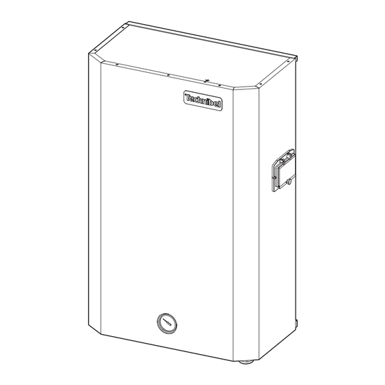
- Page 6 2.2 - DIMENSIONS AND WEIGHT AF UIH Water inlet connection 3/4” M Water outlet connection 3/4” M Water circuit fill / drain 1/2” M Safety valve connection and drainage Gas refrigerant connection 1/2” F Liquid refrigerant connection 1/4” F Holes for electric cables A (mm) B (mm) C (mm)
-
Page 7: Installation
3 - INSTALLATION 3.1 - LOCATION Minimum clearance in front of the unit: 1 m • Protection index of the unit: IP 21. • Select the location for the unit on the basis of the following criteria: - the unit must be installed in a sheltered location, - the unit must not be installed near the following: 0 . - Page 8 • Replacing the cover. - Present the cover on the unit while aligning the lower edge with the lower part of the rear support. - Fit the cover against the rear support to engage the hooks in the notches (1). - Slide the cover downward fully into place (2).
-
Page 9: Connections
4 - CONNECTIONS 4.1 - REFRIGERATION CONNECTIONS APPLIANCES FILLED WITH R 410 A R 410 A 3 - In the case of a new charge: • R 410 A is a high-pressure refrigerant (+ 50% in relation to - the charge must be undertaken in liquid phase, R 22 and R 407 C). - Page 10 • For the following information: - Maximum height between units. - Required tools. - Advice concerning the piping installation. - Connection to the outdoor unit. - Leak testing. - Vacuum operation. - Additional refrigerant charge. Refer to the installation instructions provided with the outdoor unit. •...
- Page 11 Note 2: The sizing of the power supply cables is to be ensured by the installer in accordance with the installation conditions and as per current standards. Cable sizes, indicated below, are given for information purposes. They are calculated in accordance with NFC 15-100 (² CEI 364) with the following hypotheses: - Maximum current, see table below.
- Page 12 4.3.2.2 - 400 V three-phase power supply Single-phase power supply 400 V / 3 + N + T / 50 Hz Remove the bridges Terminal XP Indoor unit Power supply amperages and cable sizes - The sections are given as an indication only. They have to be verified and adapted, if necessary, according to the installation conditions and the standards in force.
- Page 13 4.3.4 - OTHER CONTROL CONNECTIONS Caution: To avoid problems related to electromagnetic disturbances, do not route these cables near power cables. Control unit With built-in ambient temperature sensor. To be installed in zone 1. Outside air temperature Load shedding (if installed) Installation Installation Outdoor unit...
- Page 14 E) Pilot wire for electric convectors (if any) - The pilot wire sends shut-down, “anti-freeze” (long term absence) or “Economy” mode instructions to the electric convectors in zone 2, and possibly in the case of 1 floor zone or 1 terminal unit zone applications. Convector control (not supplied) must be adapted to receive this type of signal (standard GIFAM 4).
-
Page 15: Accessories
4.3.5 - ROUTING OF CABLES • To avoid problems related to electromagnetic disturbances, avoid routing control cables near power cables. • Pass the cables through the cable glands. • Route the control cables on the right side of the electric board. •... - Page 16 • Water quality: - In order for the heat pump to operate under good conditions and provide optimum performance, it is essential to ensure that the system’s water circuit is clean. If the water circuit becomes clogged, this will significantly affect the machine’s performance.
- Page 17 6.2.3 - ZONE CONFIGURATION Set microswitch SW3 according to the application, as shown in the table. CONTROL PCB A2 TYPE OF APPLICATION TERMINAL UNIT OR MIXED ZONE (Factory state) SW3: 1=OFF 2=OFF FLOOR ZONE SW3: 1=ON 2=OFF RADIATOR ZONE SW3: 1=OFF 2=ON...
- Page 18 6.3 - ADDITIONAL HYDRAULIC CIRCUIT VERIFICATIONS 6.3.1 - FORCED CIRCULATOR OPERATION • In order to conduct the final verifications of the hydraulic circuit, force the pump to start as follows (installation power ON): - Set the system control unit to “OFF”. - Temporary turn off the circuit breaker Q4.
- Page 19 FACTORY SETTING Factory setting Constant pressure curve CP2 To change the setting: • Push the button for two seconds: Pump goes to setting mode - LEDs start flashing. • Every time you push the button, the speed setting changes: LEDs 1-2-3 flash in sequence (see the figure). Fast flashing: proportional pressure (PP) Slow flashing: constant pressure (CP) •...
-
Page 20: Maintenance Instruction
7 - MAINTENANCE INSTRUCTIONS IMPORTANT NOTE • Before doing any work on the installation, make sure it is switched off and all power supplies locked out. Before disconnect the outdoor unit and then the hydrokit. • Also check that the capacitors are discharged. •... -
Page 21: System Wiring Diagram
7.5 - TROUBLESHOOTING RECOMMENDATIONS • All maintenance and servicing operations on the refrigerating circuit must be conducted in accordance with standard trade practices and safety rules: recovery of the refrigerant, inert shielded (nitrogen) brazing, etc… • All brazing operations must be conducted by qualified welders. •... -
Page 22: Wiring Diagram
9 - WIRING DIAGRAM... - Page 23 Colours of the wires Symbols of the components Blue Brown Heating control PCB Black YEL/GRN Yellow/Green Indoor unit PCB PNK Pink Violet Communication and control module RED Red Yellow Water pressostat WHT White Automatic - heater safety thermostat Manual - heater safety thermostat Water flow switch Heater fault relay Water flow relay...
- Page 24 RIELLO S.p.A. Via Ing. Pilade Riello, 7 37045 - Legnago (VR) www.thermital.it The manufacturer strives to continuously improve all products. Appearance, dimensions, technical specifications, standard equipment and accessories are therefore liable to modification without notice.
Need help?
Do you have a question about the AF UIH Series and is the answer not in the manual?
Questions and answers