Table of Contents
Advertisement
Quick Links
Pompe à chaleur avec équipement hydraulique air / eau - Fluide réfrigérant R 407 C
Heat pump with hydraulic equipment air / water - R 407 C refrigerant
Refrigeratore d'acqua in versione pompa di calore con sezione idronica incorporata
Bomba de calor con equipamiento hidráulico aire / agua - Fluido refrigerante R 407 C
Wärmepumpen reversibel mit hydraulikausrüstung Luft / Wasser zur
Mars 2008
(Etiquette signalétique)
PHRV 22 / 36
aria / acqua Fluido refrigerante R 407 C
Außenaufstellung - Kältemittel R 407 C
NOTICE
D'INSTALLATION
INSTALLATION
INSTRUCTION
MANUALE
D'INSTALLAZIONE
MANUAL
DE INSTALACIÓN
AUFSTELLUNGS-
HANDBUCH
10 11 470 - F.GB.I.E.D - 03
F
GB
I
E
D
Advertisement
Table of Contents

Subscribe to Our Youtube Channel
Related Manuals for Technibel PHRV 22


Summary of Contents for Technibel PHRV 22
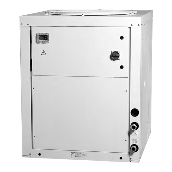
- Page 1 AUFSTELLUNGS- (Etiquette signalétique) HANDBUCH PHRV 22 / 36 Pompe à chaleur avec équipement hydraulique air / eau - Fluide réfrigérant R 407 C Heat pump with hydraulic equipment air / water - R 407 C refrigerant Refrigeratore d’acqua in versione pompa di calore con sezione idronica incorporata aria / acqua Fluido refrigerante R 407 C Bomba de calor con equipamiento hidráulico aire / agua - Fluido refrigerante R 407 C...
-
Page 2: Table Of Contents
MARKING This product marked conforms to the essential requirements of the Directives: - Low voltage no. 2006/95/EC. - Electromagnetic Compatibility no. 89/336 EEC, modified 92/31 and 93/68 EEC. SUMMARY 1 - Generalities ......... . 2 2 - Presentation . -
Page 3: Presentation
1.3 - VOLTAGE • Before carrying out any operation, check that the voltage indicated on the unit corresponds to the mains voltage. • Before initiating maintenance or servicing on the installation, check that its power supply is disconnected and locked out. 1.4 - USE OF EQUIPMENT •... - Page 4 HP and LP hose entry 2.2.1 - PHRV HP Manometer LP Manometer (Accessory) (Accessory) 1050 4 Ø 22.5 mm holes for sling attachment weight PHRV 22 303 kg PHRV 25 305 kg PHRV 32 327 kg Access to PHRV 36 363 kg switch box 2.2.2 - 150-LITRES BUFFER TANK (ACCESSORY)
-
Page 5: Installation
3 - INSTALLATION • Prior to all servicing or other actions on the equipment, installation, commissioning, operation, or maintenance, the personnel in charge of these operations shall become familiar with the instructions and recommendations provided in the installation manual of the unit as well as the elements of the project's technical file. •... - Page 6 4.2 - ELECTRICAL CONNECTIONS 4.2.1 - GENERALITIES: • In all cases, refer to the wiring diagrams supplied with the unit or supplied upon request. • The acceptable voltage variation is: ±10% during operation. • The electrical connection conduits must be fixed. •...
-
Page 7: Operation Of "Ech" Electronic Control
CAUTION: Heating control unit In this case, the maximum length of the cable is limited to 50 m. On / Off 4.2.4 - REMOTE CONTROL • See § 6.3. (Accessories). Operating mode 4.2.5 - SUPPLEMENTARY TANK HEATING • See § 6.5. (Accessories). 4.2.6 - MISCELLANEOUS •... - Page 8 5.3.2 CTN TYPE TEMPERATURE PROBE • 10 kΩ at 25° C. Temperature (°C) Ohmic value (Ohm) Temperature (°C) Ohmic value (Ohm) 67,740 8,313 42,450 5,820 27,280 4,161 17,960 3,021 12,090 2,229 10,000 5.4 - OPERATING MODES • The machine is wired in the factory to operate in heating mode. •...
- Page 9 5.6 - PARAMETERS - DISPLAYING AND ADJUSTING 5.6.1 - GENERALITIES • Parameter access is structured within a multi-level menu, see the diagram below. Simultaneously pressing the "ON/OFF" (1) and "Mode" (2) buttons for a brief moment (less than 2 seconds) gives access to the next level. Simultaneously pressing for a long moment (longer than 2 seconds) turns you to the previous level.
- Page 10 5.6.3 - SETPOINT ADJUSTMENT • Simultaneously press buttons (1) and (2) for at least 2 seconds, "SET" is displayed. • Press the 2 buttons again, "Coo" is displayed. Using button (1) or (2), display either "HEA" or "Coo" corresponding to the heating setpoint ("HEA") or cooling setpoint ("Coo").
- Page 11 SUMMARY TABLE OF ALARMS Supplementary Compressor Alarm Code Inhibition delay Fan stop Pump stop heating control Remarks stop shut-down Fault on probe 1 Fault on probe 2 Fault on probe 3 Force water pump Fault on probe 4 operation H.P. L.P.
- Page 12 • Operating mode selection: - the controller is factory configured to control the unit by 3 outside contacts: • On / Stand-by , • Heating / Cooling. - in stand-by mode, the circulating pump continues to function. Note: It is possible to shut the unit down completely (circulating pump stopped) by pressing the ON/OFF button (1). - this configuration is adapted to system applications, - for other applications, the following configurations are possible by modifying the parameterization: a) Complete shut-down ("OFF") by remote contact (instead of "stand-by").
- Page 13 • "Dynamic" set points: - by changing the parameter H31 from 0 to 1, an automatic heating and cooling set point compensation system based on the outside temperature is activated, - the following parameters allow the compensation slopes to be set: Parameter Designation Factory setting...
-
Page 14: Accessories
6 - ACCESSORIES 6.1 - VIBRATION KIT • The kit includes: - a set of four vibration pads, 25 mm thick, code 70600035, - a set of two hoses, length: 1 m, ø 1" 1/4 70600027. 6.2 - HP AND LP PRESSURE GAUGES •... - Page 15 • Connection: Connector: - the control is delivered with a connector so that the link can be blue wire = terminal 24 connected to the “ECH” controller, mounted in the unit. red wire = terminal 25 - to extend the link, max. length.: 100 meters, use twisted pair shielded black wire = terminal 26 cable with a cross section of at least 0.5 mm (shielding of the ground...
- Page 16 6.5.1 - INSTALLATION • See dimensions and weight in § 2.2. • Installation precautions in § 3. • Designed to be installed either underneath the unit, or separately. IMPORTANT: If a tank is mounted underneath the unit, never handle the assembly. The unit and the tank must be handled separately.
- Page 17 6.5.4 - ELECTRICAL CONNECTIONS: model with supplementary heating See the general information about the electrical connections in § 4.2.1. • CAUTION: in the case where the tank and the unit are mounted separately, make sure that the grounds of both equipment are interconnected.
- Page 18 - All malfunctions detected by this thermostat results in the shut- down of the electric heating. Tank PHRV 22 to 36 - After having turned off (and locked out) the power to the unit and corrected the malfunction, the safety device is reset by Security pressing the button located on the body of the thermostat.
- Page 19 OPERATION A - PRESENTATION • The following are located inside the heating control box: - the power switch to which the electric heating power supply is connected, - the power outgoing feeders, protected by circuit breakers, supplying electrical power to the Electric immersion heaters, Mode indicator...
- Page 20 B - WATER TEMPERATURE PROBES Temperature (°C) Ohmic value (Ohm) (heating option) 16,600 • CTN type 3 kΩ at 25°C. 9,796 • Probe defect: 5,971 If the temperature value measured is outside of the 3,748 measurement range (-20°C to +84°C), the indicator 3,000 light of the selected mode begins to flash and the R1 2,417...
-
Page 21: Starting
7 - STARTING IMPORTANT Before doing any work on the installation, make sure that it is switched off and that access to it is prevented. Any work must be carried out by personnel qualified and authorised to work on this type of machine. 7.1 - CHECK •... -
Page 22: Maintenance Instruction
8 - MAINTENANCE INSTRUCTIONS IMPORTANT NOTE • Before doing any work on the machine, make sure that it is switched off and locked out, with special attention given in the case of a tank with supplementary heating (different power supplies). •... -
Page 23: Circulating Pump Curves
10 - CIRCULATING PUMP CURVES PUMP TYPE MUH 503 PUMP TYPE MUH 504 PHRV 22/25 PHRV 32/36 Water flowrate (m Water flowrate (m... -
Page 24: Pressure Curves
11 - PRESSURE CURVES 11.1 - COOLING MODE LOW PRESSURE HIGH PRESSURE PHRV 22 Outside temperature (°C) Outside temperature (°C) 45°C 45°C 35°C 35°C 25°C 25°C 15°C 15°C Water outlet temperature (°C) Water outlet temperature (°C) PHRV 25 Outside temperature (°C) 45°C... - Page 25 11.2 - HEATING MODE LOW PRESSURE HIGH PRESSURE PHRV 22 Water outlet temperature (°C) 50°C 45°C 35°C Water outlet temperature (°C) 50°C 45°C 35°C Outside wet bulb temperature (°C) Outside wet bulb temperature (°C) PHRV 25 Water outlet temperature (°C) Water outlet temperature (°C)
-
Page 26: Start-Up Data Sheet
12 - START-UP DATA SHEET PHRV Code: Serial Number: Started by: Company: Site: Date: V L1-L2 L2-L3 L3-L1 Voltage measured on unit FANS Measured amperage Circuit breaker thermal setting COMPRESSORS Measured amperage A/phase L1 Circuit breaker thermal setting PUMP A/phase L1 Amperage Circuit breaker thermal setting HEAD PRESSURE CONTROL... - Page 27 - End of defrosting T/P set point -500 °C/10 150 (*) / 100 (**) /50 d05 - Max. defrosting duration d10 - Defrosting compensation activation flag d11 - Defrosting compensation offset -255 °C/10 (*) for PHRV 22 (**) for PHRV 25 (***) for PHRV 36...
- Page 28 Par souci d'amélioration constante, nos produits peuvent être modifiés sans préavis. Due to our policy of continuous development, our products are liable to modification without notice. Per garantire un costante miglioramento dei nostri prodotti, ci riserviamo di modificarli senza preaviso. En el interés de mejoras constantes, nuestros productos pueden modificarse sin aviso prévio.
Need help?
Do you have a question about the PHRV 22 and is the answer not in the manual?
Questions and answers