Table of Contents
Advertisement
Available languages
Available languages
Quick Links
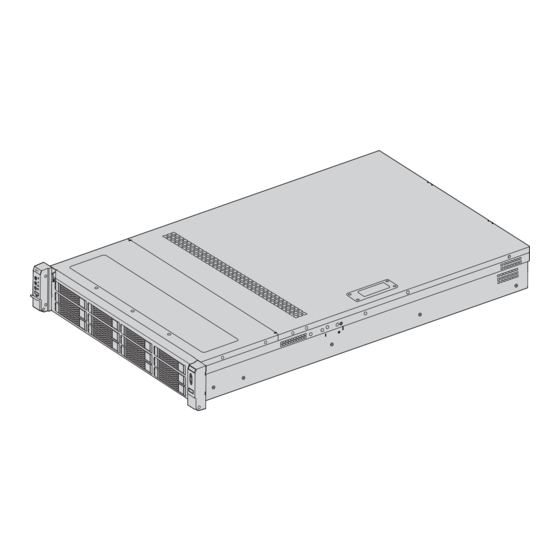
RS7250
DUAL INTEL® XEON® SCALABLE
PROCESSORS 2URACK MOUNT SERVER
ZWEI INTEL® XEON® SKALIERBARE PROZESSOREN 2HE RACK SERVER
SERVEUR À DEUX PROCESSEURS INTEL® XEON® SCALABLE 2U À
MONTAGE EN RACK
デュアルINTEL® XEON®スケーラブル・プロセッサー �Uラック
マウントサーバー
Quick Start Guide
V3.0
Quick Start Anleitung
Guide de Démarrage Rapide
クイックスタートガイド
Advertisement
Table of Contents

Subscribe to Our Youtube Channel
Related Manuals for FS RS7250


Summary of Contents for FS RS7250
- Page 1 RS7250 DUAL INTEL® XEON® SCALABLE PROCESSORS 2URACK MOUNT SERVER ZWEI INTEL® XEON® SKALIERBARE PROZESSOREN 2HE RACK SERVER SERVEUR À DEUX PROCESSEURS INTEL® XEON® SCALABLE 2U À MONTAGE EN RACK デュアルINTEL® XEON®スケーラブル・プロセッサー �Uラック マウントサーバー Quick Start Guide V3.0 Quick Start Anleitung Guide de Démarrage Rapide...
- Page 2 Introduction Thank you for choosing RS7250 Rack-mount Server. This guide is designed to familiarize you with the layout of the server and describes how to deploy the server in your network. RS7250 Accessories A pair of Gloves Power Cord x2...
-
Page 3: Hardware Overview
Hardware Overview Front Panel Information Label The Diagram of Hard Disk Sequence HDD8 HDD9 HDD10 HDD11 HDD4 HDD5 HDD6 HDD7 HDD0 HDD1 HDD2 HDD3 Buttons/Ports Number Button/ Port Description Power button. Press the button to boot the server when it’s Power powered on. -
Page 4: Back Panel
NOTE: Hz indicates the number of times a flashing light blinks per second. Back Panel LAN1 LAN2 IPMI USB3.0 Number Description Install 2.5-inch modules(optional). Support SAS/SATA//NVME hard disks. Only support one PCI-E 3.0 X8 by default. Optional two-slot kit(one X8 and one X16). 5-10 3 PCI-E 3.0X8 adapter cards. - Page 5 Motherboard The layout of the motherboard with jumper, connector and LED locations is shown as below. See the table on the following page for description. BAT1 PCIESLOT1 OCP1 SSATA5 PCIESLOT3 U37HS1 SSATA4 OCP2 MINISASHD3 PCHHS1 PCIESLOT2 MINISASHD1 JSDO8 JPWR2 MINISASHD2 OCULINK2 JPWR1 JTPM1...
- Page 6 Jumpers Description Default Setting JBAT8 Clear CMOS Pins 1-2(Restore jumper) JSDO8 Flash Memory Security Override Pin 1-2(Normal) Names Description OCP Type A Slot OCP1 OCP2 OCP Type C Slot MINISAS HD1 Intel PCH SATA 0-3 Intel PCH SATA 4-7 MINISAS HD2 Intel PCH SASTA 0-3 MINISAS HD3 Motherboard buzzer...
-
Page 7: Installation Requirements
PCI-E_SLOT3 PCI-E3.0×8(CPU1) SSATA4-5 Intel PCH SSATA 4-5 LAN1-2 Motherboard integrated network port 1-2 UID LED Node Recognition LED VGA1 Motherboard integrated VGA BCM Dedicated network port BMC_LAN1 Motherboard integrated USB3.0×3 JBUS2 Installation Requirements Before installation, make sure the following conditions are met: Mount the server on the rack. - Page 8 1. Mount the inner rail of the sliding rail on both sides of the chassis to fix the inner rail with screws. 2. Mount the outer rail of the sliding rail on the rack. 3. Lift the server up, then align it to the middle rail. 4.
-
Page 9: Removing The Top Cover
Removing the Top Cover 1. loosen the two screws on both sides of the top cover. 2. Pull the plastic buckle of the top cover upward to remove the top cover. NOTE: When mounting the top cover, press the plastic buckle down and tighten the screws on both sides of the top cover. - Page 10 #6-32 Screw 2. For 3.5 inch hard disk, fix the #6-32 screws from two sides of the hard disk tray inwards. CPU Mounting 1. Align Point B and C of the processor with point B and C of the CPU mounting bracket. 2.
- Page 11 4. Align Point a/b/c/d of the CPU with point A/B/C/D of the heat sink. 5. Insert point C/D of the heat sink into the guide pin c/d of the CPU. 6. Fasten the screws according to the order 1,2,3,4 with a 12 1bf T30 plum screwdriver.
-
Page 12: Connecting The Power
Memory Mounting A. Open the latches on both sides of the memory slot. B. Pay attention to accurately align the memory with the memory slot. C. Align the memory with the memory slot, then insert it into the slot. D. Press the memory downwards and insert it into the slot tightly. Then snap on the latches on both sides of the memory slot. -
Page 13: Bios Setting
Configuring the Rack Server BIOS Setting After startup, press < DEL > as prompted to enter BIOS SETUP. Keyboard command description table Aptio setp Utiity-copyright (C) 2021 American Megatrends Inc. Main Advanced Platform Configuration Socket Configuration Server Mgmt Security Boot BIOS Information Choose the system default Project Version... -
Page 14: Troubleshooting
Step 4: Press <Ctrl>+ <I> to enter the RAID setting during the startup self-check. Software Installation The operating system of Microsoft Windows Server 2016 and Redhat Enterprise Linux7.3 is not provided currently. For details on server configuration, see the the section of installing virtual media of the online Configuration Guide. -
Page 15: Online Resources
Check whether the power cords and signal cables of hard disks are correctly installed. Check whether all the relevant switches and jumpers on hard disk drives and adapters are set correctly. Check whether the hard disk configuration is correct. Online Resources Download https://www.fs.com/products_support.html Help Center https://www.fs.com/service/fs_support.html Contact Us https://www.fs.com/contact_us.html Product Warranty Warranty: The rack-mount server enjoys 3 years limited warranty against defect in materials or workmanship. - Page 16 Einführung Vielen Dank, dass Sie sich für den RS7250 Rack Server entschieden haben. Diese Anleitung soll Sie mit dem Aufbau des Servers vertraut machen und beschreibt, wie Sie den Server in Ihrem Netzwerk einsetzen. RS7250 Zubehör Ein Paar Handschuhe Netzkabel x2...
- Page 17 Hardware-Übersicht Vorderseite Informationsetikett Diagramm der Festplattenreihenfolge HDD8 HDD9 HDD10 HDD11 HDD4 HDD5 HDD6 HDD7 HDD0 HDD1 HDD2 HDD3 Tasten/Ports Taste/Port Beschreibung Einschalttaste. Drücken Sie die Taste, um den Server hochzufahren, Strom wenn er eingeschaltet ist. Drücken Sie die Taste 5 Sekunden lang, um den Server nach dem Hochfahren auszuschalten.
- Page 18 HINWEIS: Hz gibt an, wie oft ein Blinklicht pro Sekunde blinkt. Hinterseite LAN1 LAN2 IPMI USB3.0 Beschreibung Installieren Sie 2,5-Zoll-Module (optional). Unterstützt SAS/SATA//NVME-Festplatten. Unterstützt standardmäßig nur einen PCI-E 3.0 X8. Optionales Zwei-Slot-Kit (ein X8 und ein X16). 5-10 3 PCI-E 3.0X8 Adapterkarten. Pci-e3.0x16 und PCI-E3.0X8 sind optional. Zwei LAN1-Schnittstellen, die an Gigabit-Kabel der Kategorie 6 angeschlossen werden 11-12 können (100 MB oder weniger werden nicht unterstützt).
- Page 19 Hauptplatine Das Layout der Hauptplatine mit den Positionen der Jumper, Anschlüsse und LEDs ist unten abgebildet. Eine Beschreibung finden Sie in der Tabelle auf der folgenden Seite. BAT1 PCIESLOT1 OCP1 SSATA5 PCIESLOT3 U37HS1 SSATA4 OCP2 MINISASHD3 PCHHS1 PCIESLOT2 MINISASHD1 JSDO8 JPWR2 MINISASHD2 OCULINK2...
- Page 20 Jumpers Beschreibung Standardeinstellung JBAT8 Clear CMOS Pins 1-2 (Jumper wiederherstellen) JSDO8 Flash Memory Security Override Pin 1-2 (Normal) Beschreibung Name OCP Type A Slot OCP1 OCP2 OCP Type C Slot MINISAS HD1 Intel PCH SATA 0-3 Intel PCH SATA 4-7 MINISAS HD2 Intel PCH SASTA 0-3 MINISAS HD3...
- Page 21 PCI-E_SLOT3 PCI-E3.0×8(CPU1) SSATA4-5 Intel PCH SSATA 4-5 LAN1-2 Integrierter Netzwerkanschluss der Hauptplatine 1-2 UID LED LED zur Knotenerkennung VGA1 Integrierte VGA auf der Hauptplatine BCM Dedizierter Netzwerkport BMC_LAN1 Integriertes USB3.0×3 auf der Hauptplatine JBUS2 Installationsvoraussetzungen Stellen Sie vor der Installation sicher, dass die folgenden Bedingungen erfüllt sind: Montieren Sie den Server im Rack.
- Page 22 1. Montieren Sie die inneren Schienen der Gleitschienen auf beiden Seiten des Fahrgestells, um die inneren Schienen mit Schrauben zu befestigen. 2. Montieren Sie die äußeren Schienen der Gleitschienen auf dem Gestell. 3. Heben Sie den Server an, und richten Sie ihn an der mittleren Schiene aus. 4.
- Page 23 Abnehmen der oberen Abdeckung 1. Lösen Sie die beiden Schrauben auf beiden Seiten der oberen Abdeckung. 2. Ziehen Sie die Kunststoffschnalle der oberen Abdeckung nach oben, um die obere Abdeckung zu entfernen. HINWEIS: Wenn Sie die obere Abdeckung montieren, drücken Sie die Kunststoffschnalle nach unten und ziehen Sie die Schrauben auf beiden Seiten der oberen Abdeckung fest.
- Page 24 #6-32 Screw 2. Bei 3,5-Zoll-Festplatten befestigen Sie die Schrauben #6-32 von zwei Seiten des Festplattenfachs nach innen. CPU Mounting 1. Richten Sie die Punkte B und C des Prozessors auf die Punkte B und C der CPU-Halterung aus. 2. Richten Sie Punkt A des Prozessors mit PIN1 der CPU-Halterung aus. 3.
- Page 25 4. Richten Sie die Punkte a/b/c/d der CPU mit den Punkten A/B/C/D des Kühlkörpers aus. 5. Führen Sie den Punkt C/D des Kühlkörpers in den Führungsstift c/d der CPU ein. 6. Ziehen Sie die Schrauben in der Reihenfolge 1, 2, 3, 4 mit einem Pflaumenschraubendreher 12 1bf T30 an.
-
Page 26: Anschluss Der Stromversorgung
Speicher-Montage A. Öffnen Sie die Verriegelungen auf beiden Seiten des Speichersteckplatzes. B. Achten Sie darauf, dass der Arbeitsspeicher genau auf den Speichersteckplatz ausgerichtet ist. C. Richten Sie den Arbeitsspeicher auf den Speichersteckplatz aus und setzen Sie ihn dann in den Steckplatz ein. - Page 27 Konfigurieren des Rack-Servers BIOS-Einstellung Drücken Sie nach dem Einschalten <DEL>, wenn Sie dazu aufgefordert werden, um das BIOS SETUP aufzurufen. Beschreibungen der Tastaturbefehle Aptio setp Utiity-copyright (C) 2021 American Megatrends Inc. Main Advanced Platform Configuration Socket Configuration Server Mgmt Security Boot BIOS Information Choose the system default Project Version...
-
Page 28: Fehlersuche
Intel(R)Matrix Storage Manager option ROM V8.0.1009 ICH10R/DO wRAID5 Copyright(C) 2003-09 Intel Corporation. All Rights Reserved. MAIN MENU 1. Create RAID Volume 3. Reset Disks to Non-RAID 2. Delete RAID Volume 4. Recovery Volume Options 5. Exit DISK/VOLUME INFORMATION RAID Volumes: = Data is Encrypted None defined. - Page 29 Prüfen Sie, ob die Netz- und Signalkabel der Festplatten richtig installiert sind. Prüfen Sie, ob alle relevanten Schalter und Jumper an den Festplatten und Adaptern richtig eingestellt sind. Prüfen Sie, ob die Festplattenkonfiguration korrekt ist. Online Ressourcen https://www.fs.com/de/products_support.html Download https://www.fs.com/de/service/fs_support.html Hilfecenter https://www.fs.com/de/contact_us.htmll...
- Page 30 Garantie: Für diesen Rack-Server gilt eine beschränkte Garantie von 3 Jahren auf Material- und Verarbeitungsfehler. (Für Zubehör gilt eine beschränkte Garantie von 1 Jahr.) Weitere Einzelheiten zur Garantie finden Sie unter: https://www.fs.com/de/policies/warranty.html Rückgabe: Wenn Sie den/die Artikel zurückgeben möchten, finden Sie Informationen zur Rückgabe unter...
- Page 31 Introduction Merci d'avoir choisi le Serveur pour Rack RS7250. Ce guide est conçu pour que vous puissiez vous familiariser avec la configuration du serveur et décrit comment procéder à son déploiement. RS7250 Accessoires Une Paire de Gants Câble d'Alimentation x2...
-
Page 32: Aperçu Du Matériel
Aperçu du Matériel Panneau Frontal Information Label Le Diagramme de la Séquence du Disque Dur HDD8 HDD9 HDD10 HDD11 HDD4 HDD5 HDD6 HDD7 HDD0 HDD1 HDD2 HDD3 Boutons/Ports N° Bouton/Port Description Bouton d'alimentation. Appuyez sur le bouton pour démarrer le Alimentation serveur lorsqu'il est sous tension. -
Page 33: Panneau Arrière
NOTE : Hz indique le nombre de fois qu'une lumière clignotant clignote par seconde. Panneau Arrière LAN1 LAN2 IPMI USB3.0 N° Description Installez des modules de 2,5 pouces (en option). Support des disques durs SAS/ SATA//NVME. Supporte seulement un PCI-E 3.0 X8 par défaut. Kit à deux emplacements en option (X8 et X16). - Page 34 Carte Mère Vous trouverez ci-dessous une présentation de la carte mère avec l'emplacement des cavaliers, des connecteurs et des indicateurs lumineux. Voir le tableau de la page suivante pour les descriptions. BAT1 PCIESLOT1 OCP1 PCIESLOT3 SSATA5 U37HS1 SSATA4 OCP2 MINISASHD3 PCHHS1 PCIESLOT2 MINISASHD1...
- Page 35 Cavaliers Description Paramètres par Défaut JBAT8 CMOS Clair Broche 1-2 (Cavalier de restauration) Support de Sécurité de la Mémoire JSDO8 Broche 1-2 (Normale) Flash Description Noms Emplacement OCP de Type A OCP1 OCP2 Emplacement OCP de Type C MINISAS HD1 Intel PCH SATA 0-3 Intel PCH SATA 4-7 MINISAS HD2...
-
Page 36: Exigences D'installation
PCI-E_SLOT3 PCI-E3.0 × 8 (CPU1) SSATA4-5 Intel PCH SSATA 4-5 LAN1-2 Port réseau intégré 1-2 de la carte mère UID LED LED de reconnaissance de nœud VGA1 Carte mère intégrée VGA Port réseau dédié BCM BMC_LAN1 Carte mère intégrée USB3.0 × 3 JBUS2 Exigences d'Installation Avant de commencer l'installation, assurez-vous que vous disposez des... - Page 37 1. Montez les rails intérieurs des rails coulissants des deux côtés du châssis pour fixer les rails intérieurs avec des vis. 2. Montez les rails extérieurs des rails coulissants sur le rack. 3. Soulevez le serveur, puis alignez-le sur le rail central. 4.
-
Page 38: Montage Du Disque Dur
Retrait du Couvercle Supérieur 1. Desserrez les deux vis de chaque côté du couvercle supérieur. 2. Tirez la boucle en plastique du couvercle supérieur vers le haut pour retirer le couvercle supérieur. NOTE : Lors du montage du couvercle supérieur, appuyez sur la boucle en plastique et serrez les vis des deux côtés du couvercle supérieur. - Page 39 #6-32 Screw 2. Pour un disque dur de 3,5 pouces, fixez les vis #6-32 des deux côtés du plateau du disque dur vers l'intérieur. Montage du CPU 1. Alignez les points B et C du processeur avec les points B et C du support de montage du CPU. 2.
- Page 40 4. Alignez le point a/b/c/d du CPU avec le point A/B/C/D du dissipateur thermique. 5. Insérez le point C/D du dissipateur thermique dans la broche de guidage c/d du CPU. 6. Serrez les vis selon l'ordre 1,2,3,4 avec un tournevis 12 1bf T30.
-
Page 41: Installation De La Mémoire
Installation de la Mémoire A. Ouvrez les loquets des deux côtés de la fente de mémoire. B. Faites attention à aligner avec précision la mémoire avec la fente de mémoire. C. Alignez la mémoire avec la fente de mémoire, puis insérez-la dans la fente. D. - Page 42 Configuration du Serveur Rack Paramètre du BIOS Après le démarrage, appuyez sur la touche < DEL > pour accéder au BIOS SETUP. Tableau de description des commandes du clavier Aptio setp Utiity-copyright (C) 2021 American Megatrends Inc. Main Advanced Platform Configuration Socket Configuration Server Mgmt...
-
Page 43: Dépannage
Étape 4 : Appuyez sur <Ctrl>+ <I> pour entrer dans le paramètre RAID pendant l'autocontrôle de démarrage. Installation du Logiciel Le système d'exploitation de Microsoft Windows Server 2016 et Redhat Enterprise Linux7.3 n'est pas fourni actuellement. Pour plus de détails sur la configuration du serveur, consultez la section d'installation des supports virtuels du Guide de Configuration en ligne. -
Page 44: Ressources En Ligne
Vérifiez si tous les switchs et câbles pertinents des disques durs et des adaptateurs sont correctement réglés. Vérifiez si la configuration du disque dur est correcte. Ressources en Ligne Téléchargez https://www.fs.com/fr/download.html Centre d'assistance https://www.fs.com/fr/service/help_center.html Contactez-nous https://www.fs.com/fr/contact_us.html Garantie du Produit Garantie : Le serveur à... - Page 45 イン トロダクション RS����ラックマウン トサーバーをお選びいただき、 ありがとうございます。 このガイドは、 サーバー のレイアウ トを理解し、 ネッ トワークにサーバーに配置する方法を説明することを目的としています。 RS7250 アクセサリー 一対の手袋 電源コード x� スライディ ングレール x�...
- Page 46 ハードウエア概要 フロントパネル 情報ラベル ハードディ スク順番の図 HDD� HDD� HDD�� HDD�� HDD� HDD� HDD� HDD� HDD� HDD� HDD� HDD� ボタン/ポート 番号 ボタン/ポート 説明 電源ボタン。 サーバーの電源が入った状態でボタンを押すと、 サ 電源 � ーバーが起動します。 サーバーが起動した後、 �秒間ボタンを押す と電源が切れます。 サーバー識別インジケータボタン。 ボタンを押してIDインジケー � ターを点灯させ、 ボタンを押して消灯させます。 � BMCを再起動させるためのボタン。 �/� USB �.� USB �.�ポート。...
- Page 47 注: Hzは、 �秒あたりの点滅ライ トの点滅回数を示します。 バックパネル LAN1 LAN2 IPMI USB3.0 番号 説明 �.�インチ モジュールを取り付ける (オプション) 。 SAS/SATA//NVMEハードディ スク �-� をサポート。 デフ ォルトでは、 PCI-E �.� X�を�つだけサポート。 オプションの�スロッ トキッ ト (�つ �-� のX�と�つのX��) 。 �-�� � PCI-E �.�X�アダプタカード。 PCI-e�.�x��とPCI-E�.�X�はオプション。 カテゴリ�のギガビッ トケーブルが接続可能なLAN�インターフェース�基 (���MB以 ��-�� 下は非対応)...
- Page 48 マザーボード ジャンパ、 コネクタ、 およびLEDの位置を含むマザーボードのレイアウ トを以下に示します。 説明につ いては、 次のページの表を参照して ください。 BAT1 PCIESLOT1 OCP1 SSATA5 PCIESLOT3 U37HS1 SSATA4 OCP2 MINISASHD3 PCHHS1 PCIESLOT2 MINISASHD1 JSDO8 JPWR2 MINISASHD2 OCULINK2 JPWR1 JTPM1 JPWR11 OCULINK1 M21 JUSB5 JPWR9 JPWR12 JPWR8 JPWR7 JPWR5 JCHASSIS1 JUSB4 OCULNK3 CPU0 CPU1 OCULNK4 JPWR10...
- Page 49 説明 ジャンパー デフ ォルト設定 JBAT� CMOSクリア ピン �-�(復元ジャンパー) フラッシュメモリのセキュリティオ ピン �-�(通常) JSDO� ーバーライド 名称 説明 OCP� OCP Type Aスロッ ト OCP Type Cスロッ ト OCP� Intel PCH SATA �-� MINISAS HD� Intel PCH SATA �-� MINISAS HD� Intel PCH SASTA �-� MINISAS HD�...
- Page 50 PCI-E_SLOT� PCI-E�.� × � (CPU�) SSATA�-� Intel PCH SSATA �-� LAN�-� マザーボード内蔵ネッ トワークポート�-� ノード認識LED UID LED マザーボード一体型VGA VGA� BMC_LAN� BCM専用ネッ トワークポート マザーボード一体型USB�.�x� JBUS� 取り付け要件 取り付けの前に、次の条件が満たされていることを確認してください: サーバーをラックに取り付けます。 サーバーを取り付けるために、ラックが十分に安定していることを確認してください。 サーバーは、清潔でほこりのない、風通しのよい場所に設置する必要があります。 取り付け場所には、少なくとも�つの�極のコンセントが必要です。 サーバーは強い電磁場や電気的ノイズを発生する機器から隔離する必要があります。 サーバーのメンテナンスを容易にするためにスペースを確保します。 ご注意 : サーバーをラックに取り付けたり維持したりする際に人身事故を防ぐため、ラ ックが安定した状態に保たれるように特別な注意を払ってください。お客様の安全を確 保するために、次のガイドラインが提供されています: �. ラックに他の機器がない場合は、サーバーはラックの一番下に取り付ける必要があり ます。 �. ラックに搭載する機器(サーバーを含む)は、重量に応じて下から上に向かって搭載 してください。...
- Page 51 �. シャーシの両側にスライドレールのインナーレールを取り付け、ネジで固定します。 �. スライドレールの外側のレールをラックに取り付けます。 �. サーバーを持ち上げて、ミドルレールに合わせます。 �. サーバーを中央のレールに押し込んでください。カチッ」という音がしたら、B点の青いブ ロックを矢印の方向に引き、サーバーをラックに押し込みます。 �. C/D点でプラスチックカバーを開け、ネジを締めめます。 注 : 「カチッ」という音がしてサーバーが引き出せない場合は、A点の白いブロック またはB点の青いブロックを矢印の方向に引っ張ると、サーバーを引き抜くことがで きます。...
- Page 52 トップカバーの取り外し �. トップカバーの両側にある�つのネジを緩めます。 �. トップカバーのプラスチック製バックルを上方向に引っ張り、トップカバーを取り外します。 ご注意 : トップカバーを取り付けるときは、 プラスチック製のバックルを押し下げ、 トップカ バーの両側のネジを締めてください。 ハードディスクの取り付け M� ネジ �. �.�インチ ハードディスクの場合、M�ネジをハードディスクトレイの底面から上方向に固定 します。...
- Page 53 ネジ#�-�� �. �.�インチ ハードディスクの場合、ハードディスクトレイの�つの側面から#�-��ネジを内側に 固定します。 CPUの取り付け �. プロセッサーのB点とC点を、CPU取り付けブラケットのB点とC点に合わせます。 �. プロセッサのA点をCPU取り付けブラケットのPIN�に合わせます。 �. プロセッサをCPU取り付けブラケットに固定します。...
- Page 54 �. CPUのa/b/c/d点とヒートシンクのA/B/C/D点を合わせます。 �. CPUのガイドピンc/dにヒートシンクのC/D点を挿入します。 �. �� �bf T��プラムドライバーを使用して、�、�、�、�の順序でネジを締めます。...
- Page 55 メモリの取り付け A. メモリスロットの両側のラッチを開けます。 B. メモリとメモリスロットの位置が正確に合わせるように注意してください。 C. メモリをメモリスロットに合わせて、スロットに挿入します。 D. メモリを下向きに押し、スロットにしっかりと挿入します。その後、メモリスロットの両側 にあるラッチをはめ込みます。 E. メモリスロットの両側にあるラッチが完全にはめ込まれていることを確認します。 注: �. メモリ機能をスムーズに実現するには、 主にメモリ容量と粒子タイプに関して、 同じサ ーバーがま ったく同じメモリ製品を使用することが重要です。 �. メモリの動作周波数はCPUに依存し、 CPUによ って対応する最大メモリ周波数が異なりま す。 ����Mhzは第�世代Intel Xeon Scalable-SP (��XX,��XX) 搭載時のみサポートされます。 �. 不均衡なメモリ トポロジ。 たとえば、 一方のメモリチャネルに�つのメモリを取り付け、 もう 一方のメモリチャネルに�つのメモリを取り付けると、 メモリ性能が低下します。 電源の接続 LAN1 LAN2 IPMI USB3.0 �.
- Page 56 ラックサーバーの構成 BIOS設定 起動後、プロンプトに従って< DEL >を押してBIOS SETUPに入ります。 キーボードコマンド説明表 Aptio setp Utiity-copyright (C) 2021 American Megatrends Inc. Main Advanced Platform Configuration Socket Configuration Server Mgmt Security Boot BIOS Information Choose the system default Project Version ES212IPL2.19 language Build Date and Time 05/20/2021 16:27:14 Platform Information LBG QS/PRQ-1G-S1 Memory Information...
- Page 57 Step �: <Ctrl>+ <I>を押して、起動時のセルフチェック中にRAID設定に入ります。 ソフトウェアのインストール Microsoft Windows Server ����、Redhat Enterprise Linux�.�のOSは現在提供しておりません。 サーバー構成の詳細については、オンライン構成ガイドの仮想メディアのインストールに関す るセクションを参照してください。 トラブルシューティ ング 電源LEDが消灯している場合 すべての電源コードがしっかりと差し込まれているかどうか、電源コードがジャンクション ボックスやコンセントに正しく接続されているかどうか、ヒューズやヒューズ切れが破損し ていないかどうか、などを確認してください。 システムが正常に動作しているかどうかを確認してください。その場合、電源LEDが故障し ているか、フロントパネルからマザーボードへのケーブルが緩んでいる可能性があります。 画面に文字が表示されない場合 キーボードが正常に動作しているか、「Num Lock」LEDが点灯しているか確認します。 モニターの電源コードがしっかり差し込まれているか、電源が 入っているか確認してくだ さい。現在、多くのモニターは、動作していないときは自動的に電源が切れ、起動するとウ ォームアップ時間が必要です。 モニターの明るさ、コントラストが正しく調整されているかどうか確認してください。 モニターの設定が正しいかどうか確認してください。 モニターの信号ケーブルが正しく取り付けられているかどうかを確認してください。 オンボードビデオコントローラが正常に動作するかどうかを確認してください。 画面に間違った文字や歪んだ文字が表示される場合 モニターの明るさとコントラストが適切に調整されているかどうかを確認してください。 モニターの信号ケーブルが正しく取り付けられているかどうかを確認してください。 VGAカードの取り付けが正しいかどうかどうかを確認してください。 システムファンが正常に回転しない場合 システム冷却ファンが正常に動作しない場合、システムコンポーネントが損傷している可能性 があります。このとき、次のアイテムを確認してください: 壁のコンセントにAC電源が供給されているかどうかを確認します。 電源ボタンが押されているかどうかを確認します。...
- Page 58 ファンモーターが停止したかどうかを確認します(サーバー管理サブシステムを使用して ファンの状態を確認します)。 ファンの電源コネクタがボードに正しく接続されているかどうか、またはフロントパネルか らのケーブルがマザーボードに正しく接続されているかどうかを確認します。 電源コードがマザーボードに正しく接続されているかどうかを確認します。 短絡の原因がケーブルの圧迫か、電源コネクタの電源ジャックへの不適切な挿入によるも のかどうかを確認してください。 ハードディスクドライブのLEDが消灯している場合 ハードディスクが�つ以上取り付けられている場合は、次のアイテムを確認してください: ハードディスクの電源コードと信号ケーブルが正しく取り付けられているかどうかを確認し ます。 ハード ディスク ドライブとアダプタのすべての関連するスイッチとジャンパが正しく設定 されているかどうかを確認します。 ハードディスクの構成が正しいかどうかを確認します。 オンラインリソース https://www.fs.com/jp/products_support.html ダウンロード https://www.fs.com/jp/service/fs_support.html ヘルプセンター https://www.fs.com/jp/contact_us.html お問い合わせ 製品保証 保証: ラックマウントサーバーは、材料または製造上の欠陥に対して�年間の限 定保証を享受しています。(アクセサリーは�年間の保証が付いています。) 保証 の詳細については、以下のサイトをご参照ください: https://www.fs.com/jp/policies/warranty.html 返品: 返品を希望される場合は、以下のサイトで返品方法に関する情報をご確認 ください: https://www.fs.com/jp/policies/day_return_policy.html...
-
Page 59: Compliance Information
Die FS.COM GmbH erklärt hiermit, dass dieses Gerät mit der Richtlinie 2014/30/EU und 2014/35/EU konform ist. Eine Kopie der EU-Konformitätserklärung finden Sie unter www.fs.com/de/company/quality_control.html FS.COM GmbH déclare par la présente que cet appareil est conforme à la Directive 2014/30/UE et 2014/35/UE. Une copie de la Déclaration UE de Conformité est disponible sur https://www.fs.com/fr/company/quality_control.html FS.COM LIMITED... - Page 60 UKCA Hereby, FS.COM Innovation Ltd declares that this device is in compliance with the Directive SI 2016 No. 1091 and SI 2016 No. 1101. FS.COM LIMITED FS.COM Innovation Ltd 24F, Infore Center, No.19, Haitian 2nd Rd, 4th Floor Imperial House, 8 Kean Street,...
Need help?
Do you have a question about the RS7250 and is the answer not in the manual?
Questions and answers