Table of Contents
Advertisement
Quick Links
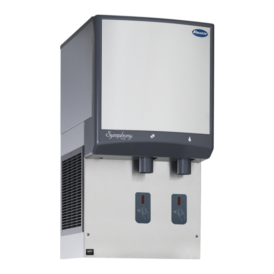
C/E25/50CI425A-SI Countertop
Ice-only Dispenser with
SensorSAFE™ Dispensing
C/E25/50CI425A-S Countertop Dispenser
with SensorSAFE™ Dispensing
Welcome to Follett
Follett equipment enjoys a well-deserved reputation for excellent performance, long-term reliability and outstanding
after-the-sale support. To ensure that this equipment delivers that same degree of service, review this guide carefully
before you begin your installation.
Should you have need technical help, please call our Technical Service group at (877) 612-5086 or (610) 252-7301.
Please have your model number, serial number and complete and detailed explanation of the problem when
contacting Technical Service.
Getting Started
After uncrating and removing all packing material. Inspect the equipment for concealed shipping damage. All freight
is to be inspected upon delivery. If visible signs of damage exist, please refuse delivery or sign your delivery receipt
"damaged." Follett Customer Service must be notified within 48 hours. Wherever possible, please include detailed
photos of the damage with the original packaging so that we may start the freight claim process.
801 Church Lane • Easton, PA 18040, USA
Toll free (877) 612-5086 • +1 (610) 252-7301
www.follettice.com
Symphony Plus
Installation, Operation and Service Manual
Please visit https://www.follettice.com/technicaldocuments
for the Operation and Service manual for your unit.
25 and 50 Series
™
Ice and Water Dispensers
C/E25CI425A, C/E50CI425A
After serial number L90016
C/E25/50CI425A-LI Countertop Ice-only
Dispenser with Lever Dispensing
C/E25/50CI425A-L Countertop Dispenser
with Lever Dispensing
Installation and Service Videos:
www.follettice.com/servicevideolibrary
01234657R03
Advertisement
Table of Contents

Related Manuals for Follett L90016


Summary of Contents for Follett L90016
-
Page 1: Welcome To Follett
If visible signs of damage exist, please refuse delivery or sign your delivery receipt "damaged." Follett Customer Service must be notified within 48 hours. Wherever possible, please include detailed photos of the damage with the original packaging so that we may start the freight claim process. -
Page 2: Table Of Contents
Welcome to Follett........ - Page 3 § This appliance must not be cleaned by a water jet. § User maintence should not be done by children. § Follett recommends a Follett water filter system be installed in the ice machine inlet water line (standard capacity #00130229, high capacity #00978957, carbonless high capacity #01050442).
-
Page 4: Specifications
Specifications Countertop Front View Right Side View Rear View 21" (53.4 cm) 24" (61 cm) 3/8" FPT condenser inlet (water- cooled only) 3/8" FPT 25CI425A/W condenser 36" outlet (water- (91.5 cm) cooled only) 3/4" FPT drain 50CI425A/W 40" (101.6 cm) 3/8"... -
Page 5: Electrical
Electrical § 220 V, 60 Hz, 1 phase, 5.5A or 230 V, 50 Hz, 1 phase, 5.5A § Connect to a dedicated circuit. § Furnished with 7 ft (2 m) power cord. Ambient Air temp* 100 F/38 C Max. 50 F/10 C Min. (Best performance below 80 F (27 C) Water temp 90 F/32 C Max. -
Page 6: Installation
Installation Before you begin § All dispensers must be installed level in both directions to ensure proper operation. § Provide proper ventilation clearances. § Countertop units provide the option of taking utilities out bottom or back of dispenser (on countertop units with legs, utilities exit from back). -
Page 7: Installing Countertop Dispensers With Bottom Exiting Utilities
Installing countertop dispensers with bottom Fig. 3 exiting utilities WARNING! § A sturdy work surface capable of supporting the entire dispenser must be used. § The work surface must be large enough to accommodate height of dispenser. § Failure to provide proper support may result in personal injury. -
Page 8: User Information
Follett recommends sanitizing the pressurized water lines prior to cleaning the ice machine/dispenser. Follett offers two kits: order P/N 01089572 when a Follett filter system with a pre-filter bowl is present, or P/N 01089580 when a Follett filter system is not present. Follow the instructions provided with the respective kits to sanitize the pressurized water lines immediately before cleaning the ice machine/dispenser. -
Page 9: Weekly
§ (2) SaniSponge™ (P/N 00131524 - single sponge) § SafeCLEAN Plus ice machine cleaner SafeCLEAN Plus Solution: Follow the directions on the SafeCLEAN Plus packaging to mix 1 gal. (3.8 L) of Follett SafeCLEAN Plus solution. Use 100 F (38 C) water. -
Page 10: Ice Machine And Dispenser
Ice Machine and Dispenser Cleaning Procedure Note: Check drains and drain cup to ensure they are open and flowing freely. 1. If ice machine was running recently, ensure that the evaporator is completely free of ice before proceeding. If there is ice in the evaporator, complete steps 2-7 using only hot water to remove the ice, then begin Cleaning Procedure again. -
Page 11: Service
Service Ice machine Operation (all models) Follett’s ice machine consists of four distinct functional systems: § Harvesting system § Water system § Electrical control system § Refrigeration system These four systems work together to accomplish the production and harvesting of ice. A problem in any one of these systems will result in improper operation of the entire ice production cycle. -
Page 12: Water System
Water system The water level in the evaporator is controlled by a fill solenoid (Fig 6) and level detecting sensors. Water sensing rods (Fig. 7) extend down into the reservoir at the end of the evaporator assembly. The system works via electrical conductivity as follows: One of the longest probes is a common. - Page 13 Fig. 7 – Water level diagram B COMMON C HIGH A ALARM LOW D LOW NORMAL OPERATING RANGE C/E25CI425A, C/E50CI425A...
- Page 14 Electrical box and control board CAUTION! § Disconnect power to unit before putting hands or arms in storage area or attempting any repair or service to equipment. Fig. 8 – Electrical component locations Fig. 9 – Control board dip switch settings Top View OFF POSITION ON POSITION...
-
Page 15: Wiring Diagram - Lever
Wiring diagram - Lever 98 BLACK 97 WHITE 44 RED 95 GREEN 94 WHITE 93 BLACK 86 WHITE 87 WHITE C/E25CI425A, C/E50CI425A... -
Page 16: Wiring Diagram - Sensorsafe
Wiring diagram - SensorSAFE 98 BLACK 97 WHITE 106 BLACK 105 WHITE 46 PURPLE 96 BLACK 44 RED 45 BLUE NEUTRAL 101 BLACK 102 WHITE 103 GREEN 96 BLACK 95 GREEN 94 WHITE 93 BLACK 105 WHITE 106 BLACK 86 WHITE 87 WHITE C/E25CI425A, C/E50CI425A... -
Page 17: Ice Machine Operational And Diagnostic Sequences
Ice machine operational and diagnostic sequences The wiring diagrams that follow illustrate the circuitry of Follett ice machines used with 25/50 series ice dispensers. Both normal operation (stages 1—8) and non-normal diagnostic sequences showing torque-out for use in troubleshooting are shown. - Page 18 Normal operation – Stage 1 - 220 V 60 Hz The 220 V 60 Hz is identical to the 230 V 50 Hz EXCEPT that the compressor output and neutral are reversed, as shown in the diagram below. The remaining Stages show only the 230 V 50 Hz applications. High Pressure Start...
- Page 19 Normal operation – Stage 2 When continuity is seen between B and C, the water valve de-energizes, the AUGER output (P4) comes on along with the MAKING ICE LED. The auger gearmotor’s start windings are energized through a current style start relay that is pulled in by the initial high current draw of the gearmotor.
- Page 20 Normal operation – Stage 4 One second (1 s) after the fan comes on, the COMPRESSOR output comes on. The compressor circuit uses both run and start capacitors along with a potential start relay. The start capacitor in energized through the normally closed contacts of the start relay.
- Page 21 Normal operation – Stage 6 Once the bin thermostat control opens, the LOW BIN LED goes out. The compressor and gear motor outputs turn off, the MAKING ICE LED goes out and the TIME DELAY LED comes on. . T.O.L. High Pressure Switch...
- Page 22 Normal operation – Stage 8 When the dwell time of 20 minutes has expired, the TIME DELAY LED goes off. If 5 seconds of ice has been dispensed and the SLEEP CYCLE LED (Symphony Plus only) is off, the ice machine will go through the normal start-up sequence when the bin level control signals the control board for ice.
-
Page 23: Diagnostic Stages
Self-flushing (when enabled) At the completion of the 20 minute time delay, the machine checks for a cumulative one hour of ice making time since the last off-cycle flush. If the cumulative ice making time exceeds one hour, the machine will energize the drain valve P19 for 60 seconds to drain the evaporator. - Page 24 T.O.L. High Pressure Switch Compressor Start Relay WHITE Compressor Electrical Box WHITE Start POWER Capacitor Relay Drain Fill LOW BIN BLACK Valve Valve MAKING ICE SLEEP CYCLE HI PRS TIME DELAY 1 2 3 4 5 6 7 8 LOW WATER YELLOW BLACK MAINTENANCE...
- Page 25 High gearmotor amps – Stage 2 If the restart is successful the board will continue to monitor the current draw on P4 for 60 minutes looking for a second high amps (above 3A) occurrence. If the ice machine runs without problems for 60 minutes and no additional torque errors occur, the ice machine will continue normal operation.
- Page 26 Loss of water During operation, the water level cycles between the normal low (D) and normal high (C) water probes - the fill valve (P21) cycling on and off. If continuity is not detected between the common probe (B) and normal low (D) within 10 seconds, the LOW WATER and TIME DELAY LEDs will come on and the machine will shut down for the one hour time delay period.
- Page 27 High refrigerant pressure Should the refrigeration pressure rise above 425 psi, the high pressure switch contacts will open. The board sees the open circuit and the HIGH PRESSURE and TIME DELAY LEDs will come on, the machine shuts down. After the one hour time delay, the machine will attempt to restart.
- Page 28 Electrical control system schematic - 230 V 50 Hz BLACK #26 WHITE #25 L2/N GRN-YEL #24 BLACK #23 BLACK #23 DISP BLACK #51 CONTACT POWER ICE AUX WATER AUX CLOSURE LOW BIN BLACK #01 MAKING ICE SLEEP CYCLE HI PRS TIME DELAY LOW WATER MAINTENANCE...
- Page 29 Electrical control system schematic - 220 V 60 Hz BLACK #26 WHITE #25 L2/N GRN-YEL #24 BLACK #23 BLACK #23 DISP BLACK #51 BLACK #51 WHITE #52 WHITE #121 WHITE #13 CONTACT POWER CLOSURE LOW BIN BLACK #01 MAKING ICE SLEEP CYCLE P14-HI PRS COMPRESSOR...
-
Page 30: Refrigeration System
§ Recharging of unit at other than factory specifications will void ice machine warranty. Refrigerant replacement requirements 1. Non-contaminated refrigerant removed from any Follett refrigeration system can be recycled and returned to the same system after completing repairs. Recycled refrigerant must be stored in a clean, approved storage container. - Page 31 Air-Cooled ice machine capacity/24hrs. - 220 V/60 Hz Air-Cooled ice machine capacity/24hrs. - 230 V/50 Hz Ambient Air Temperature F/C Ambient Air Temperature F/C lbs. lbs. lbs. 437.5 372.5 307.5 lbs. lbs. lbs. lbs. lbs. lbs. lbs. Water-Cooled ice machine capacity/24hrs. - Water-Cooled ice machine capacity/24hrs.
- Page 32 Compressor data Air-cooled 60 F/15.6 C 70 F/21.1 C 80 F/26.7 C 90 F/32.2 C 100 F/37.8 C Ambient air temperature 220 V 230 V 220 V 230 V 220 V 230 V 220 V 230 V 220 V 230 V Amperage 2.65 2.25...
-
Page 33: Dispenser Troubleshooting
Dispenser troubleshooting CAUTION! § Disconnect power to unit before putting hands or arms in storage area or attempting any repair or service to equipment. Before calling for service 1. Check that no ice is in the dispenser bin area. 2. Check that congealed ice is not causing a jam. 3. -
Page 34: Ice Machine Removal Instructions
SensorSafe Board guide Fig. 10 LEDs, when illuminated, indicate the following: PWR (board power), CLN (clean button pressed WTR and WM outputs disabled), ICE (ice dispensing activated), WTR (water dispensing activated). Terminals: L1 (incoming power, hot), L2 (neutral terminals), WTR (power terminal for water solenoid), WM (power terminal for wheelmotor), CLN (terminals for clean cycle switch). - Page 35 Fig. 13 – All models Fig. 14 4. Close main water shut off valve (Fig. 14.1). 5. Disconnect water line to fill solenoid 3. Lower drain pan protector (Fig. 13.1). Remove (Fig. 14.2). and discard shipping screw (Fig. 13.2). 6. Remove bin drain tube (Fig. 14.3). 7.
- Page 36 Fig. 17 – All models Fig. 18 – All models 11. Partially slide ice machine from dispenser (Fig. 17.1). 12. Disconnect power and bin signal twist lock connectors from ice machine electrical box. 13. Remove insulation cap (Fig. 18.1). 14. Remove vent and drain tube (Fig. 18.2). 15.
-
Page 37: Evaporator Disassembly
Evaporator disassembly Fig. 19 Note: The upper bearing, lower bearing and auger assemblies must be replaced as assemblies. The bottom and top bearing assemblies cannot be field assembled to factory specifications. 1. Disconnect power to ice machine. 2. Shut off water to ice machine. 3. -
Page 38: Evaporator Reassembly
Evaporator reassembly Fig. 20 1. Clean gearmotor boss, output shaft and shaft well. Apply grease in well 2. Install drain pan and evaporator mounting base. 3. Fill gear motor shaft well with food grade grease (Fig. 20). 4. Install condensate shield and seat against gear motor boss. -
Page 39: Replacement Parts
Replacement parts Dispenser exterior Reference Description Part # Baffle, ice 501608 Wheel, dispense (includes 501612) 502821 Bracket, ice tube 502712 Rod, threaded (includes knurled nut) 501612 Ice transport tube, 25 series 01149830 Ice transport tube, 50 series 01149848 Louver, exhaust 00192963 Drain pan 502682... -
Page 40: Wheel Motor And Drive System
Wheel motor and drive system Reference # Description Part # Wheel motor, 120V, 60Hz 501699 Washer, thrust 501026 Shaft, drive (includes key and stud) 501619 Fan blade, wheel motor 501607 Not shown Chain, pitch 67, link 00168781 Sprocket, drive shaft, 35T (includes drive shaft key) 502692 Sprocket, wheel motor, 10T 501019... -
Page 41: Dispense Chute And Splash Panel (Models With Sensorsafe Infrared Dispensing)
Dispense chute and splash panel (models with SensorSAFE infrared dispensing) Reference # Description Part # Water solenoid (includes the solenoid, fittings, screws, and mounting bracket) 01399195 Chute, ice (with Agion 00984831 ® Splash panel, SensorSAFE dispense with drain pan (includes 2 lenses) 00981365 Splash panel, SensorSAFE dispense with drain pan, ice only (includes 1 lens) 00981381... -
Page 42: Dispense Chute And Splash Panel (Models With Lever Dispensing)
Dispense chute and splash panel (models with lever dispensing) Reference # Description Part # Boot, dispense switch button (mounts on 00981217 switch) 502418 Water solenoid (includes the solenoid, fittings, screws, and mounting bracket) 01399195 Switch, dispense, ice or water, lever actuated (includes boot) 00981217 Splash panel, lever dispense 00981290... -
Page 43: Dispenser Electrical Box - Sensorsafe Models
Dispenser electrical box – SensorSAFE models Reference # Description Part # Thermostat 500514 Switch, dispenser power 502209 Switch, ice machine bin signal 502209 Board, SensorSAFE 502915 Standoff, board (4 required) 501959 Not shown Cord and plug, ice machine power (dispenser box to ice machine box) 01037878 Not shown Cord and plug, bin signal (dispenser box to ice machine box) -
Page 44: Dispenser Electrical Box - Lever Models
Dispenser electrical box – lever models Reference # Description Part # Thermostat 500514 Switch, dispenser power 502209 Switch, ice machine bin signal 502209 Not shown Cord and plug, ice machine power (dispenser box to ice machine box) 01037878 Not shown Cord and plug, bin signal (dispenser box to ice machine box) 01037944 Not shown... -
Page 45: Water And Drain
Water and drain Reference # Description Part # Valve, water shut off 01035526 Clip, shut off valve 01035534 Tee, 1/4" 502923 Elbow, 1/4" stem x 1/4" push-in 00121699 Tube, drain, hopper, 230 V/50 Hz 01054576 Tube, drain, hopper, 220 V/60 Hz 01165398 Tube, purge 01054584... -
Page 46: Water Treatment Accessories For Symphony Plus Ice And Water Dispensers
Description Part # Standard capacity filter system Not shown Follett QC4-FL4S water filter system (includes FL4S primary cartridge and head, coarse pre- 00130229 filter and head, pressure gauge, flushing valve; assembled and installed on mounting bracket), one per ice machine... -
Page 47: Ice Machine Electrical Components
Ice machine electrical components 230 V 50 Hz 220 V 60 Hz Reference # Description Part # Capacitor, run, 230 V, 50 Hz 01087162 Relay start, compressor, 230 V, 50 Hz 01087154 Board, control circuit, 230 V, 50 Hz and 220 V, 60 Hz 01111657 Switch, clean 01229418... -
Page 48: Air-Cooled Ice Machines - 230 V 50 Hz
Air-cooled ice machines - 230 V 50 Hz C/E25CI425A, C/E50CI425A... - Page 49 Part # Drier 502724 Condenser coil, A/C 01067461 Reservoir mounting bracket, a/c (After S/N L90016) 01375609 Reservoir (includes lid, gasket, fasteners, clean and vent tubing, cleaning cup) 01230630 Bracket, electrical box 01068170 Evaporator (see page 34 and 35 for complete breakdown) —...
-
Page 50: Air-Cooled Ice Machines - 220 V 60 Hz
Air-cooled ice machines - 220 V 60 Hz C/E25CI425A, C/E50CI425A... - Page 51 Part # Drier 502724 Condenser coil, A/C 01067461 Reservoir mounting bracket, a/c (After S/N L90016) 01375609 Reservoir (includes lid, gasket, fasteners, clean and vent tubing, cleaning cup) 01230630 Bracket, electrical box 01068170 Evaporator (see page 34 and 35 for complete breakdown) —...
-
Page 52: Water-Cooled Ice Machines - 230 V 50 Hz
Water-cooled ice machines - 230 V 50 Hz C/E25CI425A, C/E50CI425A... - Page 53 Not shown Iso-washer (for water regulating valve) 501810 Reservoir (includes lid, gasket, fasteners, clean and vent tubing, cleaning cup) 01230630 Reservoir mounting bracket, a/c (After S/N L90016) 01375609 Not shown Tubing, polypropylene, reservoir supply (sold by foot) 502079 Not shown Fitting, reservoir, plastic 1/4"...
-
Page 54: Water-Cooled Ice Machines - 220 V 60 Hz
Water-cooled ice machines - 220 V 60 Hz C/E25CI425A, C/E50CI425A... - Page 55 Not shown Iso-washer (for water regulating valve) 501810 Reservoir (includes lid, gasket, fasteners, clean and vent tubing, cleaning cup) 01230630 Reservoir mounting bracket, a/c (After S/N L90016) 01375609 Not shown Tubing, polypropylene, reservoir supply (sold by foot) 502079 Not shown Fitting, reservoir, plastic 1/4"...
-
Page 56: Evaporator Replacement Parts
Evaporator replacement parts FLAKER COMPONENTS HEALTHCARE C/E25CI425A, C/E50CI425A... - Page 57 Reference # Description Part # Coupling, vee band, includes nut 502735 Bearing assembly, top 502736 Loop, ice compression, beveled (see below for Flaker-specific components) 502110 Auger (see below for Flaker-specific components) 502737 Evaporator (includes insulation jacket, 502740) 01064658 Bearing assembly, bottom (includes O rings and condensate shield) 502738 O ring, bearing housing 500496...
- Page 58 C/E25CI425A, C/E50CI425A...
- Page 59 C/E25CI425A, C/E50CI425A...
- Page 60 Warranty Registration and Equipment Evaluation Thank you for purchasing Follett ® equipment. We hope you find that our equipment meets or exceeds your expectations, as our goal is to deliver high value products and services that earn your complete satisfaction! Please review the enclosed installation and operations manual.
Need help?
Do you have a question about the L90016 and is the answer not in the manual?
Questions and answers