SMC Networks ZSE40A, ZSE40AF, ISE40A - Digital Pressure Switch Manual
- Operation manual (76 pages) ,
- Manual (25 pages) ,
- Instruction manual (3 pages)
Advertisement
Safety Instructions
These safety instructions are intended to prevent hazardous situations and/or equipment damage.
These instructions indicate the level of potential hazard with the labels of "Caution", " Warning" or "Danger". They are all important notes for safety and must be followed in addition to International standards (ISO/IEC), Japan Industrial Standards (JIS) and other safety regulations.
 | Operator error could result in injury or equipment damage. |
 | Operator error could result in serious injury or loss of life. |
 | In extreme conditions, there is a possibility of serious injury or loss of life. |
Operator
|
|
|
|
|
|
|
|
|
|
|
NOTE
- The direct current power supply to be used should be UL approved as follows:
Circuit (of class 2) which is of maximum 30Vrms (42.4V peak) or less, with UL 1310 class 2 power supply unit or UL 1585 class 2 transformer. - The Pressure switch is a
![]() approved product only if it has a
approved product only if it has a ![]() mark on the body.
mark on the body.
 approved product only if it has a
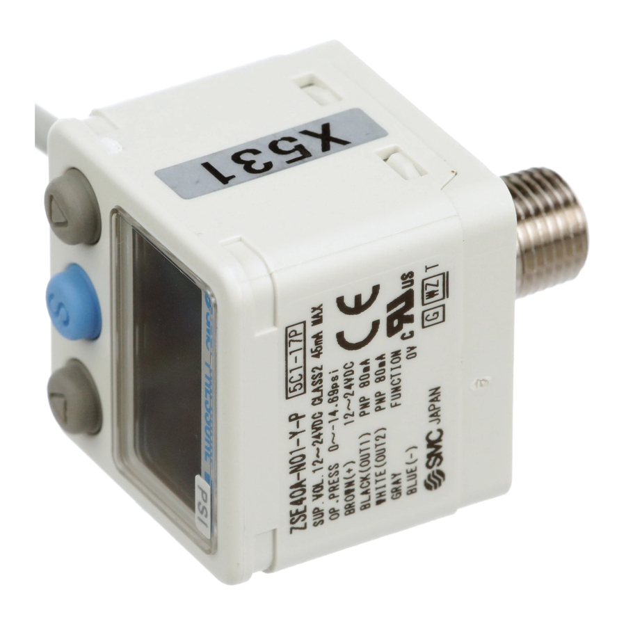
 Names and Functions of Product
Names of individual parts

Indication light (Orange LED): Displays the switch operation condition.
LCD display: Displays the current status of pressure, setting mode and error code. Four display modes can be selected to display always in red or green only, or changing from green to red, red to green according to the output status.
 button (UP): Selects the mode or increases the ON/OFF set value. Press this button to change to the peak display mode.
 button (DOWN): Selects the mode or decreases the ON/OFF set value. Press this button to change to the bottom display mode.
 button (SET): Press this button to change to either mode and to set a value.
Mounting and Installation
Installation
Mounting
- Mount the optional bracket and panel mount adapter to the pressure switch.
- When the pressure switch is to be mounted in a place where water and dust splashes occur, insert a tube into the air-relieving port of the pressure switch. (Refer to "Tube attachment")
Mounting with bracket
- Fix the bracket to the pressure switch with the set screws M3x5L (2 pcs.) or M4x5L (2 pcs.) supplied.
- Apply a tightening torque of 0.5 to 0.7 Nm for the M3 set screws or 1.4 to 1.6 Nm for the M4 set screws.
- Bracket A or D(Model: ZS-24-A/ZS-24-D)

- Bracket B (Model: ZS-24-B)
![]()
- Bracket A or D(Model: ZS-24-A/ZS-24-D)


Mounting with panel mount adapter

- Panel mount adapter
(Model: ZS-35-C/ZS-35-D)
Panel mount adapter +
Front protective cover
(Model: ZS-35-F/ZS-35-G)
Piping
Connection using screw type piping

- Connect suitable piping to the mating port.
- Hold the hexagon part of the pressure port and fix. Apply a tightening torque of 7 to 9 Nm. When using an M5 female fitting confirm the fitting specification.
Connection using One-touch fitting

- Cut the tube perpendicularly.
- Hold the tube and insert it into theOne-touch ftting slowly until it bottoms out.
- Allow sufficient tube length to prevent twist, tensile and moment load from being applied to the fitting and tube.
- When using a tube manufactured by a company other than SMC, check its outside diameter accuracy satisfies the following values.
- Nylon tube: ±0.1 mm at maximum
- Soft nylon tube: ±0.1 mm at maximum
- Polyurethane tube: +0.15 mm/-0.2 mm at maximum
Tube attachment

- When this pressure switch is used in a place where water and dust splashes may occur, insert a tube in the air-relieving port, and bring piping of the opposite side up to the safe position to keep it from water and dust. (See the figure.)
*: The tube should be inserted to the end of the air-relieving port.
*: SMC TU0425 (polyurethane, O.D ø4, I.D ø2.5) is a suitable tubing.
Wiring
Connection
- Make connection after turning the power off.
- Use a separate route when connecting the wire of the Pressure switch.
Malfunction stemming from noise may occur if the wire is installed in the same route as that of power or high-voltage cable. - Be sure to ground terminal FG when using a commerically available switch-mode power supply.
When the switch-mode power supply is connected to the Pressure switch, switching noise wil be superimposed and product specification can no longer be met. This can be prevented by inserting a noise filter, such as a line noise filter and ferrite core, between the switch-mode power supply and the Pressure switch, or by using a series power supply instead of the switch-mode power supply.

| Brown | DC(+) |
| Gray | Analog output/Auto-shift input copy terminal |
| Black | OUT1 |
| White | OUT2 |
| Blue | DC(-) |
Pressure Setting
Set ON point and OFF point of the Pressure switch.
Operation

When the pressure exceeds a set value, the Pressure switch will be turned on.
When the pressure falls below the set value by the amount of hysteresis or more, the Pressure switch will be turned off.
The default setting of the output set value is the central value between the atmospheric pressure and the upper limit of the rated pressure range. If the operation shown the right does not cause any problem, keep this operation setting.
<How to operate>
[Hysteresis mode]
- Press the
![]() button once in measurement mode.
button once in measurement mode.
![]()
- [P_1] or [n_1] and set value are displayed in turn.

- Press the
![]() or
or ![]() button to change the set value.
button to change the set value.
The![]() button is for increase and the
button is for increase and the ![]() button is for the decrease.
button is for the decrease.
 button once in measurement mode.

- Press the
![]() button once to increase by one figure, and press it continuously to keep increasing the set figure.
button once to increase by one figure, and press it continuously to keep increasing the set figure.
![]()
- Press the
![]() button once to decrease by one figure, and press it continuously to keep decreasing the set figure.
button once to decrease by one figure, and press it continuously to keep decreasing the set figure.
![]()


- Press the button to finish the setting of OUT1.
[P_2] is displayed. Set OUT2 same way as OUT1.
[ Window comparator mode ]
The Pressure switch turns on within a set pressure range (from P1L to P1H) during window comparator mode. Set P1L (switch lower limit) and P1H (switch upper limit) using the setting procedure above.
| Zero clear of indication Indication is reset to zero when  and and  buttons are pressed simultaneously for 1 second. buttons are pressed simultaneously for 1 second.For the first operation, perform zero clear without pressure supply. |
Setting of Function
Default setting
At the time of shipment, the following settings are provided.
If the setting is acceptable, keep it for use.
To change setting, refer to SMC website (URL http://www.smcworld.com) to get information in detail or contact us.
- [F 0] Unit conversion function
| Unit specification | Pressure range | Default setting |
| Nil or M | ISE40A | MPa |
| ZSE40A(F) | kPa | |
| P | ISE40A | PSI |
| ZSE40A(F) |
- [F 1] Setting of OUT1
| Item | Explanation | Default setting |
| Output mode | Selects hysteresis mode, window comparator mode or OFF mode. | Hysteresis mode |
| Reversed output | Selects reversed output. | Normal output |
| Pressure setting | Sets ON point or OFF point of the switch output | ISE40A: 0.500 MPa ZSE40A: -50.7 kPa ZSE40AF: 50.0 kPa |
| Hysteresis | Chattering can be prevented by setting hysteresis. | 5% |
| Display color | Selects the display color. | ON: Green OFF: Red |
- [F 2] Setting of OUT2
Same setting as [F 1] OUT1.
At the output mode, Error detection mode can be selected.
Display color is linked to the setting of OUT1, and can not be selected.
- Other parameter setting
| Item | Default setting |
| [F 3] Setting of response time | 2.5 ms |
| [F 4] Setting of auto-preset | Manual |
| [F 5] Setting of analog output/auto-shift input | Analog output |
| [F 6] Setting of fine adjustment of display value | 0% |
| [F11] Setting of display resolution | 1000-split |
| [F80] Setting of power saving mode | OFF |
| [F81] Setting of security code | OFF |
| [F90] Setting of all functions | OFF |
| [F97] Selection of copy function | OFF |
| [F98] Check of output | Normal |
| [F99] Reset to the default setting | OFF |
Measurement mode

The measurement mode is the condition where the pressure is detected and indicated, and the switch function is operating.
This is the basic mode, and other modes should be selected for setting change and other function setting changes.
Function selection mode

In measurement mode, press the  button for 2 seconds or longer to display [F 0]. Select to display the function setting to be changed, [F
 ].
].
Press the button for 2 seconds or longer in function selection mode to return to measurement mode.
∗: Some functions are not available depending on part number. All functions are displayed with [F  ] and followed with function description. If a function is not available for specified type, the function is displayed as [---].
Other Settings
- Peak/Bottom hold value indication
- Zero clear
- Key lock
To set each function the above in detail, refer to SMC website (URL http://www.smcworld.com) to get information in detail or contact us.
Maintenance
How to reset the product after power cut or forcible de-energizing
The setting of the product will be retained as it was before a power cut or de-energizing.
The output condition is also basically recovered to that before a power cut or de-energizing, but may change depending on the operating environment.
Therefore, check the safety of the whole facility before operating the product. If the facility is using accurate control, wait until the pressure switch has warmed up. (About 10 to 15 minutes)
Troubleshooting
Error indication function
This function is to display error location and content when a problem or an error occurs.
| Error Name | Error Display | Error Type | Troubleshooting Method |
| Over current Error |  | A load current of switch output is 80 mA or more. | Turn the power off and remove the output factor for the over current. Then turn the power on. |
| Residual Pressure Error |  | During zero clear operation, pressure over ±7%F.S. (±3.5%F.S.for compound pressure) is applied. After 1 second, the mode will reset to the measurement mode. ±1%F.S. of the zero clear range varies with individual product differences. | Perform zero clear operation again after restoring the applied pressure to an atmospheric pressure condition. |
| Pressurizing Error |  | Pressure has exceeded the upper limit of the set pressure range. | Reset applied pressure to a level within the set pressure range. |
 | Pressure has exceeded the lower limit of the set pressure range. | ||
| Auto-shift Error |  | The measured pressure auto-shift input has exceeded the set pressure range. ∗: After 1 second, the mode will reset to measurement mode. | Auto-shift input signal is invalid. Check the connected equipment and correct the signal. |
| System Error |  | Displayed in the case of an internal data error. | Turn the power off and turn it on again. If resetting fails, an investigation by SMC CORPORATION will be required. |
If the error can not be reset after the above measures are taken, then please contact SMC.
Specification
Refer to the product catalogue or SMC website (URL http://www.smcworld.com) to get information about product specifications in detail.
Outline with Dimensions (in mm)
Refer to the product catalogue or SMC website (URL http://www.smcworld.com) to get information about outline dimensions in detail.
Note: Specifications are subject to change without prior notice and any obligation on the part of the manufacturer.
© 2009 SMC Corporation All Rights Reserved
To get information in detail for operating this product, refer to SMC website (URL http://www.smcworld.com) or contact us.

Documents / Resources
References
Download manual
Here you can download full pdf version of manual, it may contain additional safety instructions, warranty information, FCC rules, etc.
Download SMC Networks ZSE40A, ZSE40AF, ISE40A - Digital Pressure Switch Manual
Advertisement


Need help?
Do you have a question about the ZSE40A and is the answer not in the manual?
Questions and answers