Table of Contents
Advertisement
Quick Links
Advertisement
Table of Contents

Related Manuals for DLS DLS-Pump 2071


Summary of Contents for DLS DLS-Pump 2071
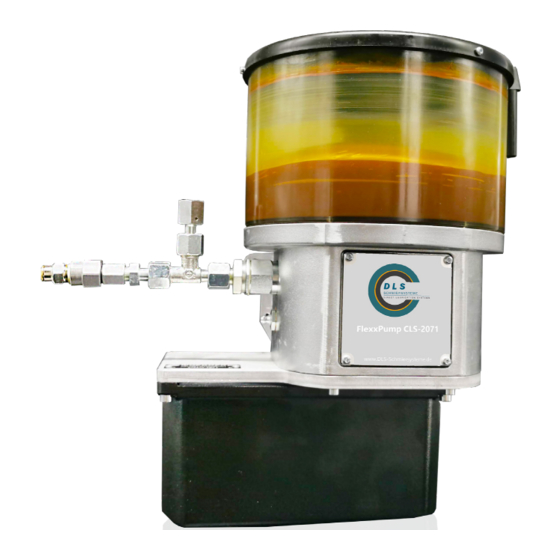
- Page 1 User manual DLS-Pump 2071...
- Page 2 Distribution and copying of this document as well as utilization and information on its content are prohibited, unless expressly permitted. Violation of this stipulation leads to payment of indemnification. All rights reserved. User manual DLS-Pump 2071 Page 2 of 30 Rev.: SG-20220427...
-
Page 3: Table Of Contents
5.3 Safety devices 5.4 Accident prevention 5.5 Residual risks 5.6 Incorrect applications 5.7 General safety regulations and duties 5.8 Disclaimer 6. Transportation, installation, commissioning and shutdown 6.1 Transportation 6.2 Unpacking User manual DLS-Pump 2071 Page 3 of 30 Rev.: SG-20220427... - Page 4 7. Cleaning, servicing, fault remedy, and repair 7.1 Cleaning 7.2 Maintenance 7.3 Inspection schedule 7.4 Refilling the reservoir 7.5 Repair 7.6 Accessories 7.7 List of spare parts 8. Return to factory 9. Disposal Clearance certificate User manual DLS-Pump 2071 Page 4 of 30 Rev.: SG-20220427...
-
Page 5: Important Notes On This Operating Manual
1.4 Operation manual 1.4.1 Applicability This operation manual is applicable to the series versions of the DLS-Pump 2071 pump units. Should any part thereof be related to particular versions only, special reference will be made. 1.4.2 Content and purpose This operation manual contains the relevant information for the commissioning, operation and mainte- nance of the pump unit. -
Page 6: Site
Notes on use as well as other useful information, which facilitate the use of the product according to its intended technical purpose. Danger! Directly imminent danger by electric power, which may lead to severe body injuries. User manual DLS-Pump 2071 Page 6 of 30 Rev.: SG-20220427... -
Page 7: Identification
2. Identification 2.1 Product brand and type designation Piston pump unit manufactured by DLS Schmiersysteme GmbH Product type: DLS-Pump 2071 2.2 Product version Version from year of construction 2021 2.3 Product designation The type plate is mounted on the side of the pump body and contains the following details:... -
Page 8: Product Description
+ 60 °C Relative humidity: max. 70% Noise level: <70 dB(A) Physical environment Use of the installation above 1000 m sea level after consultation with the manufacturer only. User manual DLS-Pump 2071 Page 8 of 30 Rev.: SG-20220427... -
Page 9: Conventional Usage
Please consider the safety data sheets of the used substances! 3.5 Technical data 3.5.1 Assemblies The GMB-B pump unit consists of up to four assemblies the different DLS-Pump 2071 versions of which may vary • Pump body with monitoring and device motor •... -
Page 10: Dimensions
3.5.2 Dimensions dimension sheet DLS-Pump 2071 Weight: with reservoir „2“ max. 6,1 kg* * without progressive distributor, without lubricant User manual DLS-Pump 2071 Page 10 of 30 Rev.: SG-20220427... -
Page 11: Basic Unit
3.5.3 Basic unit In its basic version, the DLS-Pump 2071 comprises the pump body with motor and a reservoir mounted on. The technical data of this unit is as follows: • Number of pump elements: • Delivery volume per stroke •... -
Page 12: Level Monitoring (Option)
3 W • Temperature range: 0 … +60 °C • Switching function: NC contact If inductive or capacitive loads are connected, suitable protection circuits are to be installed! (diode, RC-module, varistor) User manual DLS-Pump 2071 Page 12 of 30 Rev.: SG-20220427... -
Page 13: Electric Connection
There is a threaded connection M4 (9) on the pump housing for attaching the equipotential bonding. Skilled electricians are the only ones permitted installing the electric wiring according to DIN VDE 1000-10. User manual DLS-Pump 2071 Page 13 of 30 Rev.: SG-20220427... -
Page 14: Description Of Function
4. Description of function 4.1 Drive The pump unit DLS-Pump 2071 is driven by a direct current gear motor 5 that is flanged to the pump casing 4 from below. 4.2 Delivery function When the eccentric shaft 3 is rotating, the delivery piston 2.1 of every pump element performs a suction and delivery stroke per rotation each whilst delivering lubricant from the reservoir 1 to the lube points. -
Page 15: Function Lube Care
In some modes of operation, improvement of lubricant quality and delivery behaviour require additional stirring of the lubricant. In the DLS-Pump 2071 pump unit, such stirring is enabled by means of a specially designed eccentric drive. When the eccentric shaft 3 rotates into the one direction of rotation, the pump elements are working whilst the stirrer supplies them with lubricant. -
Page 16: Level Control (Option)
Therefore, in case of an external control, evaluation of the signal available during pump switch-on must be delayed (by approx. 5 s). Lubricant avaible No lubricant avaible (permanent signal) (intermittierendes Signal) Level control „C“ User manual DLS-Pump 2071 Page 16 of 30 Rev.: SG-20220427... -
Page 17: Safety Instructions
Only skilled technicians, who have been specifically trained for the product, are allowed inspecting, maintaining and repairing. Skilled electricians are the only ones permitted intervening in the electrical installation according to DIN VDE 1000-10. User manual DLS-Pump 2071 Page 17 of 30 Rev.: SG-20220427... -
Page 18: Safety Devices
If the pump unit is delivered in pre-filled condition, the product and safety data sheets related to the medium filled in need to be observed in addition to this operation manual. User manual DLS-Pump 2071 Page 18 of 30 Rev.: SG-20220427... -
Page 19: Incorrect Applications
Should any damage be caused to persons, objects, the environment and/or property due to the non-observance of this operation manual, no matter whether intentionally or unintentionally, DLS Schmiersysteme GmbH shall be held harmless thereof. Besides, all warranty claims will be rejected. The same also applies to any and all consequential damage. -
Page 20: Transportation, Installation, Commissioning And Shutdown
Besides, it needs to be ensured that the mounting surface is vertical and plane. Mounting holes ø 11 mm Additional mounting holes ø 11 mm Drill scheme: User manual DLS-Pump 2071 Page 20 of 30 Rev.: SG-20220427... -
Page 21: Power Supply And Switch-On
Then selecting the transmission oil, however, proper compatibility with the lubricant used needs to be ensured! User manual DLS-Pump 2071 Page 21 of 30 Rev.: SG-20220427... - Page 22 Please note: Due to the bigger distance to the filling nipple 4, the bleeding of the right-side pump element takes a little bit longer. User manual DLS-Pump 2071 Page 22 of 30 Rev.: SG-20220427...
-
Page 23: Shutdown
The unit is shut down when switched off and disconnected from the external Power supply. Skilled electricians are the only ones permitted intervening into the electrical installation according to DIN VDE 1000-10. User manual DLS-Pump 2071 Page 23 of 30 Rev.: SG-20220427... -
Page 24: Cleaning, Servicing, Fault Remedy, And Repair
„Safety regulations“ section and take effective measures to avoid injuries. Important! Also note the maintenance instructions in the operation guide-lines for the various components as they are included in the appendix. User manual DLS-Pump 2071 Page 24 of 30 Rev.: SG-20220427... -
Page 25: Inspection Schedule
To ensure flawless functioning, the filling level must not be lower than 10 … 15 mm above the reservoir’s bottom edge. min. filling level 10 ... 15 mm Reservoir bottom edge User manual DLS-Pump 2071 Page 25 of 30 Rev.: SG-20220427... -
Page 26: Repair
Unscrew the pump element cautiously. Replace the old pump element by an exchange part. When scre- wing down, be careful not to jam the connecting thread. For other repairs, turn to DLS Schmiersysteme GmbH, please. User manual DLS-Pump 2071 Page 26 of 30... -
Page 27: Accessories
Power pack for connection to 230 VAC on request Should you need cables with different cable lengths, turn to DLS Schmiersysteme GmbH directly, please. 7.7 List of spare parts See data sheet DLS-Pump 2071 Spare Parts. User manual DLS-Pump 2071 Page 27 of 30 Rev.: SG-20220427... -
Page 28: Return To Factory
The returns form P0851 must be attached. 9. Disposal When disposing the piston pump unit and its components, observe the actually current na- tional laws and provisions of the user’s country! User manual DLS-Pump 2071 Page 28 of 30 Rev.: SG-20220427... -
Page 29: Clearance Certificate
The corre- sponding safety data sheets are attached. Day of Return: _____________________________________________ Name, Position: _____________________________________________ Phone number: _____________________________________________ Date, Signature: _____________________________________________ Company stamp: _____________________________________________ Attachment: Safety Data Sheet _____________________________________________ User manual DLS-Pump 2071 Page 29 of 30 Rev.: SG-20220427... - Page 30 User manual DLS-Pump 2071 Page 30 of 30 Rev.: SG-20220427...
Need help?
Do you have a question about the DLS-Pump 2071 and is the answer not in the manual?
Questions and answers