DLS FlexxPump 125 User Manual
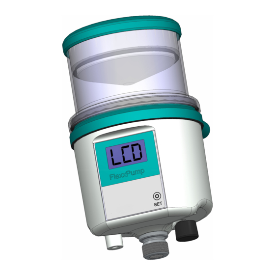
Compact double piston pump
Hide thumbs
Also See for FlexxPump 125:
- Original operating manual (40 pages) ,
- Quick start (2 pages) ,
- Manual (4 pages)

Related Manuals for DLS FlexxPump 125


Summary of Contents for DLS FlexxPump 125
- Page 1 D L S SCHMIERSYSTEME D I R E C T L U B R I C A T I O N S Y S T E M S User Manual FlexxPump 125 Power Supply (24V DC)
-
Page 2: Revision History & Imprint
01.2020 revision of the user manual: This document is protected by copyright. All rights for layout, content, texts and corporate design are reserved by DLS Schmier- systeme GmbH. All rights, including those of photomechanical reproduction, duplication and distribution by means of special processes (e.g. data processing, data carriers and data networks), even in part and/or in extracts, are reserved by DLS Schmiersysteme GmbH. -
Page 3: Table Of Contents
FlexxPump 125 (24V) D L S User Manual SCHMIERSYSTEME D I R E C T L U B R I C A T I O N S Y S T E M S I.III Table of contents Chapter Content Page Revision history &... - Page 4 FlexxPump 125 (24V) D L S User Manual SCHMIERSYSTEME D I R E C T L U B R I C A T I O N S Y S T E M S Chapter Content Page Factory settings 6.2.1 Default settings operating mode Hour-Mode -h- 6.2.2...
- Page 5 FlexxPump 125 (24V) D L S User Manual SCHMIERSYSTEME D I R E C T L U B R I C A T I O N S Y S T E M S Chapter Content Page Released accessories 10.1 Lubricants 10.2...
-
Page 6: General Information About This Manual
S Y S T E M S General information about this manual This user manual contains all necessary information to use the FlexxPump 125 in the power supply version safely and as intended. In the event that supplementary sheets are attached to these instructions, the information and data contained in the supple- mentary sheets are valid and replace the corresponding information in this user ma- nual. -
Page 7: Warning Symbols
FlexxPump 125 (24V) D L S User Manual SCHMIERSYSTEME D I R E C T L U B R I C A T I O N S Y S T E M S Warning symbols The following warning symbols are used in this user manual to alert you to hazards,... -
Page 8: Safety
FlexxPump 125 has been installed and/or fitted is prohibited until it has been clearly established that the machine complies with the provisions of the applicable Directive. An EC/EU declaration of conformity for the FlexxPump 125 can be found in the appen- dix (chapter I.II). -
Page 9: Usage For The Intended Purpose
+ Relevant regulations and rules on work safety, accident prevention and environmen- tal protection must be observed. + Work and activities with and on the FlexxPump 125 are only permitted with appropri- ate authorisation (chapter 2.3). All other uses than the aforementioned intended usage or the disregard of one of the above points shall be deemed improper usage. -
Page 10: General Safety Instructions
L U B R I C A T I O N S Y S T E M S General safety instructions The following safety instructions are given for the FlexxPump 125: DANGER Damaged or incorrect electrical connections or unauthorized live components lead to serious injuries or even death. -
Page 11: Description Of Function
Description of function General information The FlexxPump 125 is designed as an extremely compact double piston pump with grease or oil as the lubricant. The two pistons run force-controlled and counter-rotating. They are united on one outlet. The outlet is secured by an integrated non-return valve. -
Page 12: Nameplate And Designation
S Y S T E M S Nameplate and designation The nameplate of the FlexxPump 125 is visibly attached to the side of the pump itself. There the CE mark and the serial number of the FlexxPump 125 are visible. Refer to chapter 3, Fig. -
Page 13: Technical Data
FlexxPump 125 (24V) D L S User Manual SCHMIERSYSTEME D I R E C T L U B R I C A T I O N S Y S T E M S Technical data Housing Dimensions without cartridge 83 x 82 x 85 (B x H x T) -
Page 14: Transport And Storage
Transport and storage Packaging The FlexxPump 125 is delivered in an outer packaging ( cardboard box ) and - depen- ding on the scope of delivery with a lubricant cartridge and other accessories - in the same package. To protect them from moisture and dirt, they are also packed in PE films. -
Page 15: Mounting
S Y S T E M S Mounting Preparations Before starting to work, inform yourself in detail about the FlexxPump 125 using this user manual; in particular about the general safety instructions (chapter 2.7). Prepare the installation site carefully. NOTICE... - Page 16 Remove the black protective cap from the electrical M12x1 interface. 4. Connect the electrical interface Connect the FlexxPump 125 to the exter- nal power supply or controller via the M12x1 interface on the side of the FlexxPump 125 using a suitable connecting cable.
- Page 17 FlexxPump 125 (24V) D L S User Manual SCHMIERSYSTEME D I R E C T L U B R I C A T I O N S Y S T E M S 5. Unscrewing the cartridge cap. Turn the cap on the lubricant cartridge counterclockwise and pull it off.
-
Page 18: Commissioning
4. Power on If you want to put the FlexxPump 125 into operation, switch on the FlexxPump 125. Only if you switch the FlexxPump 125 on, it delivers lubricant to the lubrication point according to the settings. -
Page 19: Operation And Settings General Information
Pump 125 can also be integrated into a control system (PLC). In the Pulse-Control-Mode PUL, this controller can be used to command and control the FlexxPump 125, see Chap. 7 and Chap. 8. How to change to the operation mode PUL is described in detail in Chap. 6.3.7. -
Page 20: Factory Settings
Verify that the default settings are appropriate for your application and that the lubri- cation point is supplied with the correct amount of lubricant per time unit. If this is the case, you can operate the FlexxPump 125 with the default settings in the Hour-Mode -h-. -
Page 21: Default Setting Operating Mode Empty-Time-Mode Et
Verify that the default settings are appropriate for your application and that the lubri- cation point is supplied with the correct amount of lubricant per time unit. If this is the case, you can operate the FlexxPump 125 with the default settings in the Empty-Time-Mode Et. -
Page 22: Menu And Lcd Messages
S Y S T E M S Menu and LCD messages The LCD of the FlexxPump 125 can be used to read information optically, to change settings in conjunction with the activation and programming key on the underside of the FlexxPump 125, or to trigger individual actions. - Page 23 The graphic above illustrates the unchangeable basic flowchart of the FlexxPump 125 menu navigation as well as the options for branching to the Sub-Menus. The FlexxPump 125 can be switched on and off at several points in the menu naviga- tion. For details see chapter 6.3.3.
- Page 24 The PRO-Menu is only accessible from the ON mode (FlexxPump 125 is switched on). The PRO-Menu allows you to make changes to the FlexxPump 125 settings - and thus to its dispensing behavior. For details see chapter 6.3.9, 6.3.10 and 6.3.11.
-
Page 25: Lcd
For optical output, information in the various states is displayed on the LCD via FlexxPump 125. You will be supported by three coloured LEDs to the right of the LCD, depending on the state of the FlexxPump 125. This allows you to assess the condition of the FlexxPump 125 from a distance;... - Page 26 FlexxPump 125 is ready for operation; FlexxPump 125 dispenses lubricant in accordance to the operation mode and the set values FlexxPump 125 is ready for operation in the Pulse-Con- trol-Mode PUL and is waiting for control signal from external control (PLC)
- Page 27 FlexxPump 125 (24V) D L S User Manual SCHMIERSYSTEME D I R E C T L U B R I C A T I O N S Y S T E M S 6.3.9 PRO PRO-Menu 6.3.10 h1...240 Adjustable setting of the pause time h 6.3.11...
-
Page 28: Actions With The Activation And Programming Key
Actions with the activation and programming key The activation and programming key attached to the bottom of the FlexxPump 125 allows you to perform actions and changes in the settings of the FlexxPump 125. This activation and programming key can be easily and permanently stored underneath FlexxPump 125. - Page 29 FlexxPump 125. The hole on the bottom of the FlexxPump 125 does not necessarily have to be used to store the activation and programming key. If you want to protect FlexxPump 125 against unintentional modification or manipulation, you can also store the activation and programming key in another location.
-
Page 30: Switching On And Off
ON is displayed in the LCD. The yellow LED disappears; the LCD flashes together with the green LED twice. Ü If no error is detected during the FlexxPump 125 self-check, ON is displayed in the LCD. The green LED lights up once every 30 seconds, FlexxPump 125 is ready for operation and will dispense lubricant according to the set values. -
Page 31: Inf-Menu Operating Mode Hour-Mode -H
Insert the activation and programming key into the hole provided on the housing of the FlexxPump 125. The INF-Menu can only be accessed from the OFF mode (FlexxPump 125 is swit- ched off). When you have entered the INF-Menu, you will return to the OFF mode. -
Page 32: Inf-Menu Operating Mode Empty-Time-Mode Et
Insert the activation and programming key into the hole provided on the underside of the FlexxPump 125. The INF-Menu can only be accessed from the OFF mode (FlexxPump 125 is swit- ched off). When you have entered the INF-Menu, you will return to the OFF mode. -
Page 33: Inf-Menu Operating Mode Pulse-Control-Mode Pul
Insert the activation and programming key into the hole provided on the housing of the FlexxPump 125. The INF-Menu can only be accessed from the OFF mode (FlexxPump 125 is swit- ched off). When you have entered the INF-Menu, you will return to the OFF mode. -
Page 34: Set-Menu
125/250 Changeable parameter of the cartridge size FlexxPump 125 is switched off (OFF). Remove the activation and programming key from the bottom of FlexxPump 125 and place it on the action area. Hold the activation and programming key on the action surface. The yellow LED lights up. - Page 35 Ü The LCD flashes together with the green LED twice, whereby the operating mode is displayed in the LCD. The SET-Menu can only be accessed from the OFF mode (FlexxPump 125 is swit- ched off). When you have entered the SET-Menu, you will return to the OFF mode.
-
Page 36: Run-Menu
The RUN-Menu is used for manual activation of the FlexxPump 125. A special dona- tion from FlexxPump 125 can be triggered in this way. This function can, for example, be used for the advantageous "Quick Check" to manually check the condition of the lubrication point. - Page 37 L U B R I C A T I O N S Y S T E M S If you are in the operating mode Hour-Mode -h-, the FlexxPump 125 executes exactly as many strokes in succession after triggering the RUN function as were set in the PRO menu in the variable c.
-
Page 38: Pro-Menu Operating Mode Hour-Mode -H
(number of strokes). In principle, after the pause time h, the FlexxPump 125 executes exactly the number of strokes c (each 0.15 cm³) specified in the number of cycles c. The cycles c are evenly distributed over the dispen- sing time h. - Page 39 FlexxPump 125 (24V) D L S User Manual SCHMIERSYSTEME D I R E C T L U B R I C A T I O N S Y S T E M S Changing the value of the pause time h: ...
- Page 40 If you have made changes to the values of the pause time h or the values of the number of cycles c in the PRO-Menu and the FlexxPump 125 is otherwise ready for operation (cartridge fitted), the FlexxPump 125 will immediately start with the calculated waiting time until the next pause.
-
Page 41: 6.3.10 Pro-Menu Operating Mode Empty-Time-Mode Et
The PRO menu allows you to change the settings of the FlexxPump 125s dispensing behavior. If you are in the Empty-Ttime-Mode Et, you can change the emptying time Et in months. The FlexxPump 125 automatically calculates the pause time between two cycles to reach the set emptying time in months. - Page 42 If you have made changes to the values of the emptying time Et in the PRO-Menu and the FlexxPump 125 is otherwise ready for operation (battery full and inserted as well as a cartridge fitted), the FlexxPump 125 will immediately start with the calculated waiting time until the next dispensing.
-
Page 43: 6.3.11 Pro-Menu Operating Mode Pulse-Control-Mode Pul
S Y S T E M S 6.3.11 PRO-Menu operating mode Pulse-Control-Mode PUL The PRO menu allows you to change the settings of the FlexxPump 125's dispensing behavior. If you are in Pulse-Control-Mode PUL, no settings can be changed. The FlexxPump 125 is integrated into a control system (PLC) and commanded and control- led by the PLC (see Chap. -
Page 44: 6.3.12 Fil-Menu
S Y S T E M S 6.3.12 FIL-Menu The FIL-Menu allows you to trigger a defined multiple donation to FlexxPump 125. A total of 40 pump strokes are initiated with the activation. This function enables you to prefill connected accessories (tubes, distributors, etc.) with the lubricant contained in the lubricant cartridge, especially during the initial start-up of FlexxPump 125. -
Page 45: Error Codes
FIL prematurely with CLR. Error codes The microelectronics integrated in the FlexxPump 125 permanently monitors the status. In the event of irregularities, an addressed error message is displayed on the LCD. The red LED flashes every 5 seconds and also signals an error optically. - Page 46 I.II. If the FlexxPump 125 is in the Hour-Mode -h- or in the Empty-Time-Mode Et, the output signal in the event of an error E1...E4 is always low level (0 V) via PIN 4 of the electrical interface of the FlexxPump 125 (chapter 7.3).
-
Page 47: Input And Output Signals - Time Control
Type: M12x1 female connector; 4-pin, A-coded The FlexxPump 125 can be switched off completely by switching off the supply voltage. The settings will not be lost. The elapsed time until the next scheduled lubrication cycle is automatically stored by the FlexxPump 125 in the integrated microelectronics. After reapplying the supply voltage, the FlexxPump 125 automatically checks itself and conti- nues to operate according to the set values. -
Page 48: Output Signals At Pin 4 - Time Control
FlexxPump 125 can be processed externally. Basically, the output signals can only be sampled and must not be subjected to inductive loads or low ohmic loads. In addition to the optical display via LCD and LED on the FlexxPump 125, this also allows status control from a distance. - Page 49 (high level) are transmitted from the PLC to the FlexxPump 125 via PIN 2 in a defined sequence. The FlexxPump 125 signals the respective status to the PLC via high/low levels, which can be tapped off at PIN 4, and thus enables comprehensive control or, by suitable programming of the PLC, differenti- ated evaluation of the different statuses.
-
Page 50: Input And Output Signals - External Control (Plc)
To operate the FlexxPump 125 via an external controller (PLC) in Pulse-Control-Mo- de, a program corresponding to the communication protocol must be created in the PLC. A basic flowchart for the command of the FlexxPump 125 can be found in the appendix (chapter 11.4). -
Page 51: Input Signals - External Control (Plc)
Input signals - External control (PLC) The FlexxPump 125 provides the following unalterably defined control signals (input signals), which must be transmitted from the PLC to the FlexxPump 125 via PIN 2 of the electrical M12x1 interface as high level (+24 V DC). -
Page 52: Control Signal 2 Seconds
The FlexxPump 125 reacts only in a certain operating state to control signals at PIN 2. The operating states are output by the FlexxPump 125 via PIN 4 as a high/low level and must be tapped and processed accordingly in the PLC. - Page 53 (PLC) to the FlexxPump 125. The control signal is sent to the FlexxPump 125 by the external control (PLC). While PIN 2 of the FlexxPump 125 has a high level as input signal from the external controller (PLC), PUL is flashing in the LCD.
-
Page 54: Control Signal 12 Seconds
The FlexxPump 125 reacts only in a certain operating state to control signals at PIN 2. The operating states are output by the FlexxPump 125 via PIN 4 as high/low levels and must be tapped and processed accordingly in the PLC. - Page 55 At the end of each error-free and successful motor run (ML), the output signal at the FlexxPump 125 changes from a low level to a high level for a short pause time P = 0.5 seconds. A total of 40 engine runs and donations will take place immediately one after the other.
-
Page 56: Control Signal 14 Seconds
The control signal 14 seconds is used to acknowledge error messages of errors E2 and E3. It is the only control signal that the FlexxPump 125 can process when a low level output signal is sent. Irrespective of the basic possibility of remote acknowledgement of an error, it is essential to identify and eliminate the cause when an error message is present. - Page 57 FlexxPump 125 is ready for operation again. CLR is briefly displayed in the LCD, then PUL again. - If this internal check is not successful, the FlexxPump 125 continues to send a low level output signal. The error (E4) is still present. The error is still displayed in the LCD, the red LED continues to flash permanently.
-
Page 58: Output Signals/Lcd Messages - External Control (Plc)
FlexxPump 125 (24V) D L S User Manual SCHMIERSYSTEME D I R E C T L U B R I C A T I O N S Y S T E M S Output signals/LCD messages - External control (PLC) -
Page 59: Error E1 (Empty Level) - External Control (Plc)
Error E1 (Empty state signal) must and cannot be acknowledged. Remedial action is described in chapter 9.2. At the same time as removing the cartridge, the FlexxPump 125 sends a permanent low level (0 V) as output signal to PIN 4. - Page 60 L U B R I C A T I O N S Y S T E M S The transition of the output signals when changing a cartridge on the FlexxPump 125 in the switched-on state is shown and described below:...
-
Page 61: Error E1 (No Cartridge Mounted) - External Control (Plc)
Error E1 (No cartridge) interrupts current dispensing operations on the FlexxPump 125. The FlexxPump 125 sends a permanent low level (0 V) as output signal to PIN 4 until a cartridge is properly screwed on with FlexxPump 125 switched on. -
Page 62: Error E2 (Overload) - External Control (Plc)
LCD and the red LED lights up. When the maximum permissible pressure is reached during or after a donation, the FlexxPump 125 sends a permanent output signal as low level (0 V) to PIN 4 for exter- nal control (PLC). -
Page 63: Error E3 (Undervoltage) - External Control (Plc)
The Pulse-Control-Mode PUL is activated on the FlexxPump 125, E3 is displayed in the LCD and the red LED lights up. If the supply voltage is too low, the FlexxPump 125 sends a permanent output signal as low level (0 V) to PIN 4 for external control (PLC). -
Page 64: Error E4 (Critical Error) - External Control (Plc)
Error E4 (Critical error) - External control (PLC) Error E4 (Critical error) indicates that the integrated microelectronics has detected a critical error and that the FlexxPump 125 is not operating within the valid parameters. The cause can be mechanical, electronic or any other influencing variable. -
Page 65: Maintenance And Disposal
(see Chapter 2) and observe the relevant local and operational safety regulations. Do not deactivate any protective device without authorization! Maintenance schedule The following maintenance schedule must be observed for the FlexxPump 125: Maintenance Commis- After 500 Every... -
Page 66: Visual Check
Check the condition of the lubrication point for correct supply of lubricant. Replace damaged or defective parts immediately to ensure permanent lubrication. Check the filling level of the cartridge on the FlexxPump 125. Check possible error messages on the FlexxPump 125 and remedy the causes accordingly. 9.1.2 Cleaning ... -
Page 67: Cartridge Change
The cartridge can be changed during normal operation of the FlexxPump 125. Apart from changing the cartridge, no other measures are necessary! FlexxPump 125 has a fault (Error E1); the red LED flashes every 5 seconds. revision: 0... - Page 68 1. Unscrew the empty cartridge from the FlexxPump 125. Turn the empty cartridge counterclockwi- se from the FlexxPump 125 and dispose it properly after completion of the work. Pay attention to cleanliness during the work. Make sure that dirt and foreign bodies do not get into the lubricant inlet.
-
Page 69: Disposal
LED. A separate confirmation is not necessary. The green LED flashes briefly every 5 seconds. Ü The FlexxPump 125 automatically returns to the last active mode (ON or OFF) befo- re the completion of this work. -
Page 70: Released Accessories
This may necessitate ch- anges to the factory and/or the default settings of the FlexxPump 125 to ensure reliable and proper operation of the FlexxPump 125 together with the hydraulically connected accessories. - Page 71 FlexxPump 125 (24V) D L S User Manual SCHMIERSYSTEME D I R E C T L U B R I C A T I O N S Y S T E M S 134-200-000 bracket for Flexx- universal bracket; Pump 125...
-
Page 72: Lubricants
FlexxPump 125 and the lubrication point (or distributor). If the case arises that you cannot mount the FlexxPump 125 directly on or at the lubri- cation point, contact the manufacturer to verify your application. The influence of tem- perature, the grease used, the hoses and accessories used does not allow a general statement to be made about the possible hose length on the FlexxPump 125. -
Page 73: Appendix
FlexxPump 125 (24V) D L S User Manual SCHMIERSYSTEME D I R E C T L U B R I C A T I O N S Y S T E M S Appendix 11.1 Dimension sheet and installation dimension (15.5) -
Page 74: Ec/Eu Declaration Of Conformity
FlexxPump 125 (24V) D L S User Manual SCHMIERSYSTEME D I R E C T L U B R I C A T I O N S Y S T E M S 11.2 EC/EU Declaration of conformity revision: 0... -
Page 75: Spare Parts
FlexxPump 125 (24V) D L S User Manual SCHMIERSYSTEME D I R E C T L U B R I C A T I O N S Y S T E M S 11.3 Flowchart Pulse-Control-Mode PUL The adjacent figure illustrates the basic... - Page 76 SCHMIERSYSTEME D I R E C T L U B R I C A T I O N S Y S T E M S DLS Schmiersysteme GmbH Gewerbering 5 D-82140 Olching Tel: +49-(0)89 650 69-0 Fax: +49-(0)89 650 69-29 mail@ DLS-Schmiersysteme.de...
Need help?
Do you have a question about the FlexxPump 125 and is the answer not in the manual?
Questions and answers