DLS FlexxPump 125 Original Operating Manual
Hide thumbs
Also See for FlexxPump 125:
- User manual (76 pages) ,
- Quick start (2 pages) ,
- Manual (4 pages)

Related Manuals for DLS FlexxPump 125


Summary of Contents for DLS FlexxPump 125
- Page 1 FlexxPump 125 (24 V) Original Operating Manual Valid for products with the article number: 135-125-100 135-125-210...
- Page 3 Masthead / Copyright This documentation is protected by copyright. All rights for layout and corporate design reserved by © DLS Schmiersysteme GmbH 2017. All rights for contents and texts reserved by DLS Schmiersysteme GmbH 2017. All rights including photomechanical reproduction, copying and distribution by special processes (for example data processing, data media and data networks), even in part, reserved by DLS Schmiersysteme GmbH.
-
Page 4: Table Of Contents
Error E2 (no cartridge) ..............32 7.2.4 Transition from error E1 to error E2 ..........33 7.2.5 Erorr E3 ..................33 7.2.6 Erorr E7 overpressure ..............34 DISPOSAL ..................35 DECLARATION OF CONFORMITY ..........36 BA FlexxPump 125 - 24 V_20181121_EN de 201811... - Page 5 BA FlexxPump 125 - 24 V_20181121_EN de 201811...
-
Page 6: Safety
Observe the following points for use of the FlexxPump 125 for the intended purpose: • The FlexxPump 125 is only approved for industrial use. • The FlexxPump 125 may only be used in accordance with the technical data (see 3.3 Technical Data). -
Page 7: Assembly
Safety Assembly Have the FlexxPump 125 connected only by a trained electrician. Pay attention to the appropriate torques and assembly dimensions during assembly, see 3.3 Technical Data. BA FlexxPump 125 - 24 V_20181121_EN de 201811... -
Page 8: Scope Of Supply
• This operating manual • Quickstart Guide for quick starting with factory settings The scope of supply may include optional accessories. Individual customer parameters may have been pre-set at the factory at the customer’s request. BA FlexxPump 125 - 24 V_20181121_EN de 201811... -
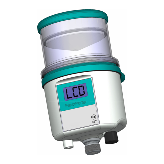
Page 9: Product Description
Product Overview Sensor probe for cartridge Field of activity M12x1-connection Lubricant feed Magnetic pin Type plate Hydraulic connection / outlet M5 thread for rear mounting 10 M5 thread for mounting from below BA FlexxPump 125 - 24 V_20181121_EN de 201811... -
Page 10: Functional Description
Product Description Functional Description The FlexxPump 125 has a double piston pump. The two pistons run in opposite directions whereby one piston sucks in the lubricant respectively whilst the other one pumps the quantity sucked in by the previous stroke to the outlet. 0.15 cm³ of lubricant is pumped per displacement or metering cycle. -
Page 11: Installation And Commissioning
6. Remove the magnetic pin (B). 7. Hold the magnetic pin against the area of activity unitl "FIL" appears. Ventings starts 8. Remove the magnetic pin (B) and put it back into the holder 1 MAX BA FlexxPump 125 - 24 V_20181121_EN de 201811... - Page 12 Installation and Commissioning 9. Connect the lubricating line. 10. OPTIONAL: Fill the lubrication line see step 7. BA FlexxPump 125 - 24 V_20181121_EN de 201811...
-
Page 13: Operation
The maximum pressure must be reduced depending on the used system and connected lines (e.g. hoses). If the set maximum pressure is exceeded, the FlexxPump 125 goes into fault status and stops the current lubricating cycle. The LCD displays a message which is output to the external controller. -
Page 14: U (Cartridge Size)
The parameter F indicates whether a signal is output to an external controller during a pumping process (motor running). The parameter depends on parameter E. For the setting E0 (factory setting), the FlexxPump 125 sends a low-level signal to an external controller during the pumping process, the pumping process cannot be detected in the controller. -
Page 15: Selection Of Parameters T And C
Operation Selection of Parameters t and C Note The emptying time t can only be set in the FlexxPump 125 if it not controlled by an external controller (Pu0). Emptying time t for 125 cm³ cartridge (U12) t (months) Lubricant quantity... -
Page 16: Menu Structure
Operation Menu Structure The fi gure below shows the complete menu structure of the FlexxPump 125. Action by user, LED fl ashes red FlexxPump 125 is ready for once operation but not switched on Sequence / reaction in the menu... -
Page 17: Switching Flexxpump 125 On/Off
On flashes twice in the LCD. The green LED flashes, the FlexxPump 125 is in operation The FlexxPump 125 feeds lubricant according to the presettings for t and C. If the LCD displays PAU, the FlexxPump 125 receives no signal from an external controller. -
Page 18: Changing Parameters In The Standard Menu (Pro)
A description of the individual parameters can be found in chapter 5.1 Adjustable Parameters. Note The emptying time t can only be set in the FlexxPump 125 if it not controlled by an external controller (Pu0). Changing parameters 9 FlexxPump 125 in operation (PAU / On) 1. -
Page 19: Triggering A Single Lubrication Process
Operation Triggering a Single Lubrication Process You can trigger a single lubrication process with the FlexxPump 125 at any time during operation. 9 FlexxPump 125 in operation (PAU / On) 1. Hold the magnetic pin against the area of activity. -
Page 20: Triggering The Filling Function
Operation Triggering the Filling Funktion You can trigger the filling function of the FlexxPump 125 for filling or venting. The FlexxPump 125 then performs 40 pumping processes automatically with a total lubricant quantity of 6 cm³. You can abort the filling function again manually. -
Page 21: Changing Parameters In The Expert Menu
A description of the individual parameters can be found in chapter 5.1 Adjustable Parameters. Note The emptying time can only be set in the FlexxPump 125 if it not controlled by an external controller (Pu0). BA FlexxPump 125 - 24 V_20181121_EN de 201811... - Page 22 The set value flashes twice. The next parameter is displayed in the LCD. The current value flashes twice if the parameter is not changed. The FlexxPump 125 automatically switches to standby after the last parameter. BA FlexxPump 125 - 24 V_20181121_EN de 201811...
-
Page 23: Changing The Cartridge
The display in the LCD changes from E1 to E2. The LED flashes red. 2. Screw on a new, full cartridge until the label faces forward. An interrupted dosing process is continued. The LED flashes green. BA FlexxPump 125 - 24 V_20181121_EN de 201811... -
Page 24: Messages And Faults
Messages and Faults Messages and Faults The following messages can appear in the LCD of the FlexxPump 125. LCD display Meaning Remedy The FlexxPump 125 is connected and ready for operationt The FlexxPump 125 is connected and waiting for a... -
Page 25: External Control
Control Signals (PIN 2) This chapter describes the signals for controlling the FlexxPump 125 by an external controller. The values and settings refer to the factory settings of the FlexxPump 125, see 5.1 Adjustable Parameters. The FlexxPump 125 is controlled exclusively by high level signals at PIN 2. -
Page 26: Signal 2Sec (Single Pump Stroke)
3 s before a control signal can be sent to the FlexxPump 125. • The 24-V signal 2sec (1.9 s ... 2.1 s) can then be sent to the FlexxPump 125. • After the signal drops to 0 V, the pump motor starts running and the FlexxPump 125 pumps lubricant. -
Page 27: Signal 3Sec (Two Pump Strokes)
• At the end of the first pumping process, the FlexxPump 125 sends a pause signal (P=0.5 s). Then the second motor run starts. • The FlexxPump 125 can process the next signal 3 s after the end of the second motor run at the earliest (pause time Tp at least 38 s). -
Page 28: Signal 4Sec (C Pump Strokes)
(P=0.5 s). Then the second motor run starts. The process is repeated C times. • The FlexxPump 125 can process the next signal 3 s after the end of the Cth motor run at the earliest (pause time Tp at least (C x 17.5) + 4 s). -
Page 29: Signal 6Sec / 12Sec (Filling/Venting Process)
(P=0.5 s). Then the second motor run starts. The process is repeated 40 times. • The FlexxPump 125 can process the next signal 3 s after the end of the last motor run at the earliest (pause time Tp at least (40 x 17.5) + 6 s). -
Page 30: Signal 10Sec (Acknowledge Error Massage)
• The 24-V signal 10sec (9.9 s ... 10.1 s) can then be sent to the FlexxPump 125. • After the signal drops to 0 V, the error is cleared, the LCD shows CLr. -
Page 31: Output Signals (Pin 4)
24 V > 3 s Description: • The electronics in the FlexxPump 125 count the dosing processes according to the used cartridge. 833 dosing processes are possible when using a 125 cm³ cartridge and 1,666 with a 250 cm³ cartridge. -
Page 32: Error E2 (No Cartridge)
> 3 s Description: • The sensor probe of the FlexxPump 125 detects whether a cartridge is screwed onto the FlexxPump 125. The capacity is not detected. • The error E2 interrupts current dosing processes and prevents further control signals. -
Page 33: Transition From Error E1 To Error E2
> 3 s Description: • If the supply voltage is too low, the FlexxPump 125 sends a permanent low-level signal, no more control signals are processed. • The error message must be acknowledged with the 10sec signal after the error has been cleared. -
Page 34: Erorr E7 Overpressure
> 3 s Description: • On reaching the set maximum pressure, the FlexxPump 125 sends a permanent low-level signal, no more control signals are processed. • The error message must be acknowledged with the 10sec signal after the error has been cleared. -
Page 35: Disposal
Observe the lubricant manufacturer’s safety data sheets and disposal notes when disposing of empty cartridges and dispose of the empty cartridges according to local regulations. Note It is not possible to refill empty cartridges. BA FlexxPump 125 - 24 V_20181121_EN de 201811... -
Page 36: Declaration Of Conformity
Declaration of Conformity Declaration of Conformity BA FlexxPump 125 - 24 V_20181121_EN de 201811... - Page 37 Declaration of Conformity Notes BA FlexxPump 125 - 24 V_20181121_EN de 201811...
- Page 38 Declaration of Conformity Notes BA FlexxPump 125 - 24 V_20181121_EN de 201811...
- Page 39 BA FlexxPump 125 - 24 V_20181121_EN de 201811...
- Page 40 DLS Schmiersysteme GmbH Gewerbering 5 82140 Olching Deutschland Phone +49 (0) 8142 - 65069-0 Fax +49 (0) 8142 - 65069-29 mail@DLS-Schmiersysteme.de www.DLS-Schmiersysteme.de...
Need help?
Do you have a question about the FlexxPump 125 and is the answer not in the manual?
Questions and answers