Table of Contents
Advertisement
Quick Links
Advertisement
Table of Contents

Related Manuals for Kubota PECO 28120901


Summary of Contents for Kubota PECO 28120901
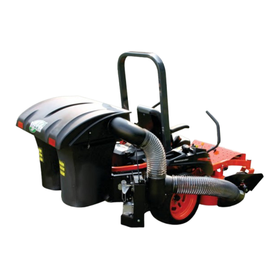
- Page 1 P P P P P P PTO DRIVEN - GRASS PECO PECO PECO PECO PECO COLLECTION SYSTEM Model# 28120901 Kommander 48” & 54” DECKS MODEL YEAR: 2015-NEWER Model# 49131505 (629JI-001A) OPERATOR’S MANUAL ASSEMBLY OPERATION MAINTENANCE Rev.4 - OCT 2022 MANUAL PART#: Q0493...
-
Page 2: Table Of Contents
GRASS COLLECTION SYSTEM TABLE OF CONTENTS SECTION PAGE SECTION PAGE Safety - - - - - - - - - - - - - - - - - - - - - - - - - - - - - - 2 Blower Cone Installation - - - - - - - - - - - - - - - - - - - 17 Safety Alert Symbols - - - - - - - - - - - - - - - - - - - - - - 3 Boot Installation - - - - - - - - - - - - - - - - - - - - - - - - - 17... -
Page 3: Safety Alert Symbols
SAFETY WARNING! NEVER operate the mower unless the discharge guard and either the deflector assembly or the vacuum collector adapter are fastened securely in place. WARNING! Do not work around the mower deck boot or the blower area until you are certain that the mower blades and the blower impeller have stopped rotating. -
Page 4: Warranty
PECO LIMITED WARRANTY FOR NEW PRODUCTS New PECO, Inc. extends the following warranties to the ORIGINAL PURCHASER of each New PECO, Inc. consumer product purchased from one of our Dealers or directly from New PECO, Inc., subject to the following limitations: A. -
Page 5: Introduction And Description
Section I - INTRODUCTION AND DESCRIPTION Introduction Description We are pleased to have you as a PECO customer. Your The grass collection system is designed for turf collection system has been designed to give you a low maintenance where there is a need to collect the grass maintenance, simple, and effective way to collect the clippings as the mower cuts the turf. -
Page 6: Preparation Of Mower
Section II - INSTALLATION FOR USE The engine pulley assembly must be installed using an Preparation Of Mower arbor press or equivalent. During installation, opposite bearing inner race must be supported or bearing NOTE: The mower deck PTO belt must be removed damage may occur. -
Page 7: Rear Mount Plate Installation
5/16” U-Bolt Rear Mount Plate Installation Attach Rear Mount Plate P#(B0902) to rear of mower using (2) 3/8-16 x 3-1/2” U-Bolts P#(K0407) and (4) 3/8”-16 Ny- Flange Locknuts P#(K2038). Next, attach to the top lip of the Mount Plate using (2) 5/16”-18 x 2” x 2- 1/2”... -
Page 8: Lower Frame Tube Installation
Lower Frame Tube Installation Attach both Lower Frame Tubes P#(B0752) by using (4) 5/16”-18 x 2.5” U-Bolts P#(K1098) and (8) 5/16”-18 Ny- Flange Locknuts P#(K2516). Refer to Figure A. Tighten the U-Bolt nuts from the Right Frame Plate installation on the previous page. Figure A Lower Frame Tubes... -
Page 9: Upper Frame Assembly Installation
Upper Frame Assembly Installation Position the Upper Frame Assembly P#(A2047) above the Lower Mount Tubes as shown in Figure A. Slide the Upper Frame Assembly down onto the Lower Mount Tubes and secure using (2) Clevis Pins P#(K0133) and (2) Hair Pin Clips P#(K0088). -
Page 10: Pto Assembly Installation
PTO Assembly Installation Figure B Remove (3) 1/4”-20 x 1/2” HHSTS P#(K0353) from the PTO assembly to remove the belt guard. Insert the Gear Box mount rod of the PTO assembly, into the mounting slots Base Plate on the PTO mount plates, as shown in Figure A. Figure A Loosen Bolts... -
Page 11: Front Baffle Installation (48" Deck)
Front Baffle Installation (48” Deck) Front Baffle Installation (54” Deck) CAUTION To avoid personal injury: - Disengage the PTO, stop the engine, remove the key and wait for all moving parts to stop - Never operate the mower without a discharge cover or grass-catcher boot installed. 1. -
Page 12: Safety Interlock Installation
3. Acquire adequate access to the bottom of the mower Switch Mount Snap Mount deck by raising the mower deck to the “carry” position. Bracket Switch P#(B0839) P#(P0265) 4.Install the front baffle assembly using the existing 2- M8 x 16 square neck bolts with 2 - M8 flange nuts. Fully tighten both fasteners. - Page 13 Fuel Line and Grommet Wire Harness Mower’s Safety Switch Lapbar Disconnect Mower’s Safety Switch here and connect Safety Interlock Harness Between.
-
Page 14: Top Assy To Upper Frame Assy Installation
Top Assembly To Upper Frame Assembly Installation Align the Top Assembly Pivot Holes to the Upper Frame Assembly. See Figure A below. Before fastening, pull Rubber Dust Guard outward to seal against Upper Frame Assembly (towards the mower’s operator seat). Fasten the Top Assembly to the Upper Frame Assembly using (2) 5/16”-18 x 2-1/2”... -
Page 15: Hinge Kit Assy Installation
Hinge Kit Assembly Installation Assemble the Hinge Kit using (1) Latch Plate P#(B0884), (1) 5/16”-18 x 1-1/4” HHCS P#(K1156), (1) 5/16”-18 Ny- Flange Lock Nut P#(K2516), (3) 5/16” Flat Washers P#(K0042), (1) Latch Spacer P#(S0006), (2) Extra Heavy 5/16” Fender Washers P#(K0505) and (1) 5/16”-18 Lock Nut P#(K0506). Leave the nuts loose enough to allow fluid movement of the top when opening and closing. -
Page 16: Bag Assembly
Bag Assembly First, take one of the Bag Ring Split Ends and insert it through the Bag Seam Opening. Next, rotate the Bag around the Bag Ring (1) full turn (360 degrees) until the Bag Ring Split Ends and the Bag Seam Opening are positioned on the same side. -
Page 17: Blower Cone Installation
Blower Cone Installation Align the bolt holes of the Blower Cone (Item#1) to the bolt holes located on the Blower Housing of the PTO Assembly. Secure the Blower Cone to the Blower Housing by using (3) 1/4”-20 x 3/4” HHCS (Item #4), (3) 1/4” Lock Washers (Item #3), and (3) 1/4”... -
Page 18: Length Of Hose Adjustment
Length Of Hose Adjustment Lower Hose To Blower Cone Installation The hoses in steps must be cut to fit your machine. Do not cut the hoses until you have tried to fit them on your Slide a pre-assembled hose clamp over both ends of the machine. -
Page 19: Impeller Blade Removal/Replacement
Impeller Blade Removal/Replacement WARNING Removal Before REMOVING/REPLACING the Impeller Blades, be sure the Mower is TURNED OFF, Step 1: Remove the blower cone from the blower housing located on the PTO assembly. With the blower cone the PTO Assembly is DISENGAGED and removed, you will have access to the impeller blade The Negative Cable is REMOVED from the assembly. -
Page 20: Weight Kit Installation
Weight Kit Installation Place (2) U-Bolts P#(K0289) through the holes on the front side of Weight Bracket P#(B0941) and start (2) 1/2”-13 Ny-Flange Locknuts P#(K2012) on the backside of the Weight Bracket. Next, place Weight Bar P#(B0704) through U- Bolts and tighten firmly. Place Weight Bracket on front of footrest and secure using (2) 5/16”-18 x 1” Carriage Bolts P#(K1144) and (2) 5/16”-18 Ny-Flange Locknuts P#(K2012). -
Page 21: Exploded Views & Parts List
A2101 Top Assembly / Standard Exploded Parts View... - Page 22 A2222 Top Assembly / Base Exploded Parts View...
- Page 23 A2194_01 PTO-R Base Assy Exploded Parts View...
- Page 24 A2194_01 PTO-R Base Assy Exploded Parts List...
- Page 25 A1137_01 PTO-R Handle Ext. Kit Exploded Parts View...
-
Page 27: Safety Decals
SAFETY DECALS To promote safe operation, New PECO, Inc. supplies safety decals on all products manufactured. Damage can occur to safety decals either through shipment, use or reconditioning. Contact your local Service Center for replacement decals. P P P PECO PECO PECO PECO... -
Page 28: Operating Instructions
SECTION III Disengagement Of The PTO Assembly OPERATING INSTRUCTIONS A. To disengage the PTO assembly, move Bagger PTO switch to the off position. General Safety WARNING: The PTO assembly blades will continue to spin. DO NOT TOUCH the PTO assembly, pulleys, or Only qualified people familiar with this operator’s manual and the mower’s operator’s manual should operate this the belt until the tractor is turned off. -
Page 29: Lubrication
3. Make sure all shields are in place and in good Lubrication condition. Repair or replace any missing or damaged shields. Gearbox: NOTE: The gearbox is filled with 6.0 oz. of Mobilube 4. Perform lubrication per instructions. HD Plus 80W-90 oil and permanently sealed. There is no need for scheduled lubrication. -
Page 31: Troubleshooting
Troubleshooting 2017 (v1.0) Collection System Performance Problem Possible Cause Corrective Action — Cutting blades are bent or — Install new cutting blade unbalanced — Loose blower pulley or pulley Abnormal Vibration — Tighten the pulley assembly — Contact dealer to replace —... - Page 32 P P P P P P PECO PECO PECO PECO PECO New PECO, Inc. 10 Walden Dr | Arden, North Carolina 28704 Phone: 1-800-438-5823 | 828-684-1234 Fax: 828-684-0858 Email: peco@lawnvac.com Website: www.lawnvac.com...
Need help?
Do you have a question about the PECO 28120901 and is the answer not in the manual?
Questions and answers