
Subscribe to Our Youtube Channel
Related Manuals for Kubota TE8511C


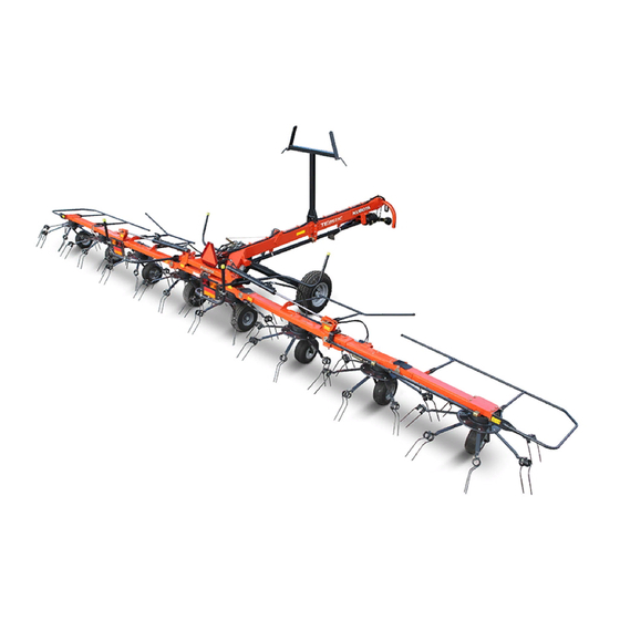
Summary of Contents for Kubota TE8511C
- Page 1 TE8511C Operator‘s manual Original operator‘s manual Edition 09.2013 Date of print 09.2014 Language EN-EU Machine number VF69120680 – Model VF6912 Document number VF16661369.EN-EU...
- Page 2 Machine identification In order for your dealer to assist you as efficiently as possible, you will need to provide some information about your machine. Please enter the details here. Designation TE8511C Working width 11.00 m (36 ft) Weight 1795 kg (3892 lb)
-
Page 3: Table Of Contents
Table of contents Table of contents Preface ............Parking and storage ........Target group for Setting down the this operating manual machine in a secure position Symbols used Uncouple and secure the machine After the end of the season Safety ............For your safety Maintenance .......... -
Page 4: Preface
Preface Target group for Preface Simplified illustrations for better understanding this operating Illustrations of the machine in the operating manual are shown without protective equipment – or with the protective equipment manual open – for better understanding. Be sure to observe the safety information and follow the handling instructions in the operating manual. -
Page 5: Symbols Used
Preface Symbols used In this operating manual, the following symbols and terms have been used: • A bullet point accompanies each item in a list. A triangle indicates operating functions which must be performed. → An arrow indicates a cross-reference to other sections of this manual. -
Page 6: For Your Safety
Safety For your safety This chapter contains general safety instructions. Each chapter of the Safety operating manual contains additional specific safety information which is not described here. Observe the safety information: • in the interest of your own safety, • in the interest of the safety of others, and •... - Page 7 Safety Warning signs (ISO) Warning signs in the ISO standard. Safety-related stickers attached to the machine indicate potential hazards. The stickers must not be removed. Illegible or missing stickers should be replaced. You can obtain new stickers as replacement parts from your dealer. Warning signs on the machine...
- Page 8 Safety Meaning of warning signs Read the operating manual Read and follow the operating and safety instructions before using the machine for the first time. The machine must not be used for the first time until the operating manual has been read and understood. This applies in particular to the safety information.
- Page 9 Safety PTO shaft speed 540 rpm The specified maximum PTO shaft speed of 540 rpm must not be exceeded. Otherwise, damage to the machine may be caused as a result. Do not exceed the maximum hydraulic pressure The tractor's hydraulic pressure on the machine's hydraulic system must not exceed 210 bar.
-
Page 10: Who Is Allowed To Operate The Machine
Safety Who is allowed to Only qualified personnel Only qualified persons who have been informed of the dangers operate the associated with handling the machine are permitted to operate, machine? service or repair the machine. This knowledge can be gained via agri- cultural training, technical training or intensive instruction. - Page 11 Safety Switch off the PTO shaft drive when raising the machine Switch off the tractor's PTO shaft drive if people could enter the working area of the machine when you • raise the machine, • raise the side devices or •...
- Page 12 Safety Never work on the machine while it is running No operations may be performed on the machine while it is running. Objects or persons can be caught, drawn in or crushed. Serious or fatal injury may be caused as a result. Safe distance from raised and unsecured loads Never work under suspended loads.
- Page 13 Safety PTO shaft speed 540 rpm The specified maximum PTO shaft speed of 540 rpm must not be exceeded. A higher PTO shaft speed will damage the machine. Do not use PTO shafts with disconnect couplings Only use PTO shafts which have been specified by the manufacturer. Other PTO shafts with disconnect couplings may allow higher disconnect torques.
-
Page 14: Coupling
Safety Coupling Increased risk of injury When the machine is being coupled to the tractor, there is an increased risk of injury. Therefore: • Secure the tractor against rolling away, shut off the engine and remove the ignition key. • Never stand between the tractor and machine. -
Page 15: Road Transport
Safety Road transport Ensuring road safety The machine must conform to current national traffic regulations if you intend to drive with it on public roads. Ensure the following: • Lighting, warning and protective equipment must be fitted. • The permissible transport widths and weights, axle loads, tyre load-bearing capacities, laden weights and national speed restric- tions must be complied with. -
Page 16: Operation
Safety Check hitch pins Hitch pins must be in perfect condition. Hitch pins must show no signs of wear and be properly secured. Otherwise, hitched machines may detach themselves of their own accord. Accidents with serious or fatal injuries may be caused as a result. Check release cables on quick-release couplings Release cables must hang loose and must not trigger a release in their lowered... -
Page 17: Uncoupling
Safety Uncoupling Increased risk of injury There is an increased risk of injury when uncoupling the machine from the tractor. Therefore: • Secure the tractor against rolling away, turn off the engine and remove the ignition key. • Never stand between the tractor and machine. •... -
Page 18: Care And Maintenance
Safety Care and Observe the care and maintenance intervals Observe prescribed intervals for maintenance checks and inspections maintenance specified in the operating manual. If these periods are not observed, damage to the machine and accidents may be caused as a result. Use original parts Machine components have special properties that are essential for the stability and correct operation of the machine. -
Page 19: Further Regulations
Safety Further Observe the regulations In addition to the safety instructions listed above, please observe the regulations following: • Accident prevention regulations. • Generally recognised safety regulations, occupational health requirements and road traffic regulations. • The instructions provided in this operating manual. •... -
Page 20: Familiarising Yourself With The Machine
Familiarising yourself with the machine Range of This product is classified as replaceable equipment in accordance Familiarising yourself with the machine with EC directive 2006/42/EC. application of the machine The machine is a rotary tedder that is solely to be used for tedding, turning and swathing mown, stalked material such as straw and hay. -
Page 21: Designation Of Components
Familiarising yourself with the machine Designation of components 1st side device Guard bar Centre device 2nd side device Hydraulic cylinders Outer device Warning signs Guard frame Rotor Transport stowage point 2-point attachment carrier Parking stand Running wheel Mainframe Transport wheel Transport chassis... -
Page 22: Technical Specifications
Familiarising yourself with the machine Technical specifications Dimensions Work position (m) Transport position (m) Length (L 5.95 (19.5 ft) Length to chassis axle (L 3.80 (12.5 ft) : 11.30 (37.1 ft) : 2.98 (9.78 ft) Width (W) Height (H 3.30 (10.83 ft) Reflector height (R) 1.18 (3.90 ft) Raking width (W... - Page 23 Familiarising yourself with the machine Weights Transport position Total weight 1795 kg (3985 lb) Supported load on the attachment carrier 175 kg (388.5 lb) Transport chassis load 1620 kg (3564 lb) Tractor equipment required Output / connections Minimum output of the tractor 40 kW (55 hp) Voltage supply for lighting equipment 12 V, 7-pin plug socket ISO 1724...
- Page 24 Familiarising yourself with the machine Machine equipment Rotors / tine arms / tines Number of rotors Number of arms per rotor Tine adjustment Mechanical Hydraulically controlled clearance of the field edge Standard Tine saver Wheels Centre device running wheel axles 18.5 x 8.50-8 Imp.
-
Page 25: Delivery And Assembly
Delivery and assembly Checking the Delivery is in the fully assembled state Delivery and assembly The machine is delivered fully assembled. Using the check list, check scope of delivery the loose parts on delivery. If any parts of the machine have not been fitted or are missing, please contact your dealer. -
Page 26: Length Of Pto Shaft
Delivery and assembly Length of PTO The length of the PTO shaft was selected at the factory to suit almost all types of tractor. Only in exceptional cases is a correction of the PTO shaft shaft length required on individual tractors. Check the length of the PTO shaft on each tractor prior to first use. - Page 27 Delivery and assembly Shortening the PTO shaft Pull the PTO shaft apart and connect one half to the tractor PTO shaft drive and one to the machine and secure them. Place the two shaft halves next to each other and: •...
-
Page 28: Coupling The Machine
Coupling the machine Safety Coupling the machine Observe the safety information Disregard for safety information can lead to serious or fatal injury. See chapter "Safety", page 6. Increased risk of injury When the machine is being coupled to the tractor, there is an increased risk of injury. -
Page 29: Swivelling In The Parking Stand
Coupling the machine Tractors without quick-release coupling The following applies to all tractors – with or without quick- release couplings: Couple the machine to the lower link - in accordance with the operating manual of the tractor manufacturer - lift slightly and secure. -
Page 30: Coupling The Pto Shaft
Coupling the machine Coupling the PTO shaft When coupling the PTO shaft, make sure it is in the correct position. PTO shaft Check whether the PTO shaft must be shortened before coupling. Shorten the PTO shaft if necessary. → "Checking the length of the PTO shaft", page 26. Check that the tractor's PTO stub shaft is clean and lubricated. -
Page 31: Wheel Wedges
Coupling the machine Wheel wedges Secure the tractor against rolling away Never remove the wheel chocks if the tractor is not otherwise secured against rolling away. Persons could be run over by the machine or the tractor. Serious or fatal injury may be caused as a result. - Page 32 Coupling the machine Hydraulic Check hoses and couplings connections Check all hydraulic hoses for damage before connecting them. Check all hydraulic couplings for firm seating after connecting them. Defective hydraulic hoses and poorly fitting hydraulic connections can trigger unpredictable movements of the machine, causing severe damage to the machine as well as personal injury.
- Page 33 Coupling the machine Connecting the Ensure the connection is correct hydraulic couplings Ensure that the hydraulic system is connected correctly. Otherwise, injuries and damage to the machine may be caused as a result. Close the ball valve. Set the tractor hydraulics to “free float”. Secure the tractor against rolling away, shut off the engine and remove the ignition key.
-
Page 34: Preparing For Operation
Preparing for operation Safety The following applies to all preparations for operation: Preparing for operation Observe the safety information Disregard for safety information can lead to serious or fatal injury. See chapter "Safety", page 6. Secure the machine Secure the machine against accidental starting and rolling away. Use wheel chocks. - Page 35 Preparing for operation General The following applies when performing all adjustment work: • Check the tyre pressure. • Secure the machine. • Lower the machine to its work position. • Undo the appropriate bolts. • Make the required adjustment. • Retighten the bolts.
- Page 36 Preparing for operation Adjusting the rotor Secure the machine pitch Secure the machine against inadvertent starting and rolling. The machine must be standing on firm and level ground and, if necessary, be supported during the work. Unsecured or non- supported machines can cause accidents. Never work under the rotors Do not carry out work on raised rotors unless they have been secured.
- Page 37 Preparing for operation Folding the machine into Switch on the tractor. the maintenance Switch off the tractor PTO stub shaft drive. position Use the tractor's hydraulic control device to fold the machine into its work position. Align the running wheels by driving forwards. Aligning the running wheels Raise the transport chassis using the tractor's single-acting Raise the transport chassis...
- Page 38 Preparing for operation Adjusting the tines The ejection angle of the tines is optimised using taper washers as required. This function enables consistent, uniform and optimum work Transport chassis results. The smaller the angle, the steeper and stronger the tine position.
- Page 39 Road transport Safety Before transporting the machine on public roads, please read the Road transport following safety information. Compliance is mandatory and will help you to avoid accidents. Observe the safety information Disregard for safety information can lead to serious or fatal injury. See chapter "Safety", page 6.
- Page 40 Road transport Observe transport width Observe the permissible transport widths. Fold the machine into the transport position and attach lights, warning signs and protective equipment. The driver and keeper of the vehicle are liable for any non-compliance with national traffic regulations. Clean lighting equipment before travelling on the road All lighting equipment must be cleaned before road transport.
-
Page 41: Prior To Road Transport
Road transport Prior to road When driving on the road, the machine must be in the transport position. The following steps are necessary to set the machine to the transport transport position: Remove any crops and coarse dirt. Fold up the machine Ensure that hydraulic connections are correct Before folding up the machine, make sure that the hydraulics for the folding device are correctly connected to a double-acting... - Page 42 Road transport Open the ball valve. Set the tractor's single-acting hydraulic control device for the transport chassis to neutral position. Using the tractor's double-acting hydraulic control device, swivel the side devices inwards at an elevated engine speed until all hydraulic cylinders are fully retracted. Transport position It is not necessary to reset the angled position.
-
Page 43: Road Transport
Road transport Checking the Prior to driving on the road, check the machine against the check list: machine Side devices safely stowed on the transport stowage point? Chassis cylinders completely extended? Tractor control system for hydraulics "OFF"? Tractor's PTO stub shaft drive off? Ball valves all closed? Locks checked for firm seating? Tyre pressures correct? - Page 44 Preparations on the field Safety The following applies for all preparations on the field: Preparations on the field Observe the safety information Disregard for safety information can lead to serious or fatal injury. See chapter "Safety", page 6. Switch off the tractor and secure it Before you dismount: Switch off the tractor.
-
Page 45: General
Preparations on the field General The following worksteps are described in this section: • Fold the machine into its work position. • Adjust rotor pitch. Folding the After road transport, the machine is brought into the work position on the field. Follow the handling instructions below: machine into the work position Folding out the... - Page 46 Preparations on the field Lift cylinder in centre position For tractors with control devices with floating position Centre position Using the tractor's double-acting hydraulic control device, fold the side devices down fully until the pin is approximately in the centre Elongated hole of the elongated hole.
-
Page 47: Operation
Operation Safety Operation Observe the safety information Disregard for safety information can lead to serious or fatal injury. See chapter "Safety", page 6. No riding on the machine Persons or objects must never be transported on the machine. Carrying passengers on the machine is life-threatening and prohibited. -
Page 48: Crop Processing
Operation Crop processing The following methods of crop processing are possible with the rotary tedder: • Tedding. • Turning. • Night swath laying. • Swath laying • Night swath turning. Tedding Turning Night swath laying When tedding, the freshly cut crop Turning ensures uniform drying of Night swathing... -
Page 49: Using The Machine
Operation Using the machine No persons in the working area Ensure that no persons are present in the slewing and working area of the machine. Persons could be caught by the machine within this area. This could result in fatal injury. After setting the machine as described in chapter "Preparations on the field"... - Page 50 Operation Working speed Prevent crossing swathes As a general measure, prevent the crossing of mowing swathes. The crop is distributed unevenly and the machine is subjected to abrupt stresses. Damage to the machine may be caused as a result. Allow ample space when driving around obstacles Obstacles must be circumnavigated in good time and at a distance.
-
Page 51: Driving On Headlands
Operation Driving on Observe the contour of the terrain headlands Pay even more attention when driving on an incline. Avoid inclines on which the combination (tractor and machine) could slip or overturn. There is an increased risk of tipping and injury in a position at right angles to the direction of the slope. - Page 52 Operation Border tedding system Watch for obstacles When driving around obstacles or along fences ensure a sufficient distance is kept. A collision may cause damage to the machine. Take care when cornering in the border tedding position Note the limited curve radius in the border tedding position. A curve radius which is too tight can cause damage to the machine.
- Page 53 Operation Working in the border Watch for obstacles tedding position When driving around obstacles or along fences ensure a sufficient distance is kept. A collision may cause damage to the machine. Take care when cornering in the border tedding position Note the limited curve radius in the border tedding position.
-
Page 54: Cleaning And Care
Cleaning and care Safety The following applies to all cleaning and care work: Cleaning and care Observe the safety information Disregard for safety information can lead to serious or fatal injury. See chapter "Safety", page 6. Secure the machine • Before starting cleaning operations, always switch off the tractor's PTO shaft drive and secure it against accidental restarting. -
Page 55: Cleaning
Cleaning and care Cleaning Switch off the tractor PTO shaft drive. Use the tractor's hydraulic control device to fold the machine into its work position. Leave the machine coupled to the tractor's lower links. Lock the tractor's hydraulic control device. Switch off the tractor and secure it. -
Page 56: Parking And Storage
Parking and storage Setting down the When setting down and parking the machine, special safety Parking and storage precautions have to be observed: machine in a secure position Observe the safety information Disregard for safety information can lead to serious or fatal injury. See chapter "Safety", page 6. -
Page 57: Uncouple And Secure The Machine
Parking and storage Uncouple and secure the machine The machine must be uncoupled in the reverse order to that in Parking stand in working which it was coupled. position → Chapter "Coupling the machine", section "General", page 28 Stop the machine in the work position on firm, secure, level ground. Close the ball valve and release the hydraulic couplings. -
Page 58: Maintenance
Maintenance Safety The following applies to all maintenance work: Maintenance Observe the safety information Disregard for safety information can lead to serious or fatal injury. See chapter "Safety", page 6. Requirements for maintenance work Only perform the maintenance work if you have the required expert knowledge and suitable tools. - Page 59 Maintenance Protective measures Additives in oils and lubricants may have adverse effects on health. As marking in accordance with the hazardous goods regulation is not when handling oils or necessary, please always ensure the following: lubricants Avoid skin contact Avoid skin contact with these materials. Protect your skin by means of protective skin cream or oil-resistant gloves.
-
Page 60: General
Maintenance General This information relates to general maintenance work. For all maintenance work, the machine must be locked in the work position. If the transport position is required for maintenance work, refer to the relevant instructions for the work. Lower the machine to the work position. Secure the machine against rolling away by using chocks. - Page 61 Maintenance Maintenance terms Listed in this table are short explanations of the most important maintenance terms. Task Explanation Greasing Apply grease to the slide surfaces using a brush. Lubrication One or two presses of the grease gun, unless specified otherwise Unless specified otherwise, use only plant-based oils, such as rapeseed oils.
- Page 62 Maintenance Maintenance intervals General • • • All screws • • • Visual inspection • • • Bearing • • • "Tyre pressure" • • • "Hydraulic hoses" • • • Lighting equipment Lubrication • • • • "Lubrication points for grease" •...
-
Page 63: Screwed Connections
Maintenance Screwed connections Tightening bolts All bolts must be retightened: • After the first 5 hours of operation and • According to the frequency of use, • But at least once a season. Special tightening Observe the special tightening torques for the following screwed con- nections: torques 90 Nm (66 ft.lbs) - Page 64 Maintenance • 20 Nm (15 ft.lbs) running wheel nuts. 20 Nm • 290 Nm (215 ft.lbs) chassis wheel nuts. 290 Nm Tightening torques for screwed connections Use the correct screw and bolt tightening torque Securely tighten screws, nuts and bolts to the specified torques. Otherwise, damage to the machine and serious or fatal injury may be caused as a result.
-
Page 65: Lubrication Points For Grease
Maintenance Lubrication points Working with a grease gun Before applying the grease gun for grease • Clean grease fittings on the machine and gun fittings on the grease gun. Lubricate the bearings with one or two presses of the grease gun. If you feel resistance at the second press, do not press a second time. -
Page 66: Lubricating The Pto Shafts
Maintenance Lubricating the The manufacturer's own operating manual is attached to each PTO shaft. This includes detailed information on the relevant version of the PTO shafts PTO shaft. Check the guard components Check all guard components of the PTO shafts for wear or damage (visual inspection). -
Page 67: Lubrication Points For Oil Lubrication
Maintenance Lubrication points Check the oil level of the main gear box and rotor gears regularly. → "Checking the main gear box", page 68 for oil lubrication → "Controlling the rotor gear", page 68 If there is visible oil loss, the gear boxes must be checked and refilled. The points presented in the illustration show the check position of the gears: Rotor gear... -
Page 68: Filling Quantities
Maintenance Filling quantities Observe the correct fill quantities Observe the correct lubricant fill quantities. Check them regularly. A lubricant level which is too low or too high may result in damage to the machine. The main gear box and rotor gear require no maintenance. Only check the oil level if there is visible oil loss when the machine is in a horizontal position. -
Page 69: Tine Position
Maintenance Tine position The tines should be fitted at a defined angle (97°) so that optimum crop collection can be achieved. The correct tine setting can be checked using the tine gauge. Checking the tine position Check the tine position for each tine Tine support Place the tine gauge on the tine support. -
Page 70: Tyres
Maintenance Tyres Do not drive with worn or damaged tyres Replace worn or damaged tyres immediately. There is a high risk of accident especially when driving on the road with such tyres. Tyre pressure Check the tyre pressures on a regular basis: •... -
Page 71: Hydraulics
Maintenance Hydraulics Hydraulic system at zero pressure Work must only be performed on the hydraulic system if the tractor and machine hydraulic system is at zero pressure. A pressurised hydraulic system can trigger unpredictable movements of the machine and can cause serious damage to the machine and personal injury. -
Page 72: Additional Equipment
Additional equipment You can purchase additional equipment through your dealer. Additional equipment Tine saver If tines are broken, the tine savers can prevent the broken-off part from being lost. Broken-off tine parts in the crop may damage machines that are following behind. •... -
Page 73: Spare Wheel
Additional equipment Spare wheel The spare wheel [+] is fitted on the outer device. Spare wheel... -
Page 74: Fault Elimination
Fault elimination Faults can often be eliminated quickly and easily. Before calling Fault elimination Customer Service, refer to the table to check whether the fault is one you can eliminate yourself. Faults Causes Remedy → "Adjusting the working depth", page Rotor is leaving crop behind Working depth set too high across the entire width... -
Page 75: Circuit Diagrams
Circuit diagrams Hydraulic circuit Circuit diagrams diagram Tank line Pressure line Tractor Single-acting control device with floating position Double-acting control unit Chassis cylinder Cable-controlled ball valve Slave cylinder with border tedding cylinder Slave cylinder Master cylinder... -
Page 76: Lighting Equipment Circuit Diagram
Circuit diagrams Lighting equipment circuit diagram 2/54g 3/31 5/58R 6/54 7/58L Connecting plug 7-pin in accordance with ISO 1724 Yellow Green White Brown Black Connectors and sockets 7-pin in accordance with ISO 1724 Yellow Black Right indicator Right brake light Earth Left indicator Right rear light... -
Page 77: Decommissioning
Decommissioning Disposal During decommissioning, the individual parts must be disposed of Decommissioning properly and in an environmentally friendly manner. Please observe the waste disposal guidelines that are currently in force. Plastic parts Plastic parts can be disposed of in normal household waste (residual waste), depending on the laws specific to your country. -
Page 78: Ec Declaration Of Conformity
DK-5300 Kerteminde Denmark declare with sole responsibility that the product CondiMaster 11041 Fanex 1103 C 80110 C TE8511C and its accessories Model: VF6912 Type plate and CE marking Valid from machine number: VF69120680 – to which this declaration relates, comply with the relevant basic health and safety requirements of EC Directive 2006/42/EC. -
Page 79: Index
Index Index Additional equipment Parking and storage Parking the machine Uncouple and secure the machine Preparing for operation Care Proper use Cleaning PTO shaft Connection Coupling Electrical Lubrication Direction information Safety Disposal Hitching Metal parts Operation Plastic parts Road transport Unhitching Speed Explanation...
Need help?
Do you have a question about the TE8511C and is the answer not in the manual?
Questions and answers