Advertisement

TO THE READER
This workshop manual provides safety information for service activity, general information such as specifications and dimensions of the machine, mechanisms and structure descriptions of the machine, and service procedures.
Safety
This section contains safety service descriptions and safety label information.
General
This section contains general instructions, tightening torques, general machine information and special tools.
Maintenance
This section contains information for the recommended oil and general maintenance procedures.
Each section basically consists of mechanism and servicing.
Mechanism
Mechanism part contains information and explanations for the structure, functions, and specifications of the machine or component parts. This part should be comprehended before proceeding with troubleshooting, disassembling, assembling, and servicing works.
Servicing
Servicing part contains information and procedures for maintenance, troubleshooting and repair works. The reader should follow these instructions in order to satisfy any servicing work safely, correctly and quickly.
In this WSM, service specifications and service limits are defined as followings.
Service specifications:
Specification which corresponds to new machine's ex-factory. It is based on quality standard, drawings, or actual measurements conducted by Kubota. This value is used to determine whether there is a problem with the machine in the event of a troubleshooting. However, it is necessary to consider degradation due to wear, based on the operating time of the machine, application or maintenance condition.
Service limits:
Service limit is a value corresponding to the recommended performance limit by taking long term-use wear into account. When the service limit is reached, the machine is required to have proper repair, overhaul or replacement in order to keep safe and adequate performance.
All of the illustrations, photographs, specifications, and other information in this manual were created based on the latest model at the time of publication.
The parts names used in this manual are unified into names representing the functions of the parts. Therefore, it does not necessarily correspond to the names used in other materials (parts list, operators manual etc.) and the name on the label / identification plates on the product.
Kubota reserves the right to change all information at any time without notice.
ABBREVIATIONS
| Abbreviations | Definitions | Abbreviations | Definitions |
| A/C | Air Conditioning | ID | Inner Diameter |
| AC | Alternating Current | ISO | International Standards Organization |
| ACC | Accessory | J/C | Joint Connector |
| AFS | Air Flow Sensor | JIS | Japanese Industry Standard |
| AI | Auto Idle | LCD | Liquid Crystal Display |
| API | American Petroleum Institute | LED | Light Emitting Diode |
| Approx. | Approximately | LH | Left Hand side |
| AS | Auto Stop | LSD | Limited Slip Differential |
| ASSY. | Assembly | MAX | Maximum |
| ASTM | American Society for Testing and Materials | MIL | Military Standards |
| AUX | Auxiliary | MIN | Minimum |
| C/V | Control Valve | NC | Normally Closed |
| CAB | Cabin | NO | Normally Opened |
| CAN | Controller Area Network | OD | Outer Diameter |
| CCV | Closed Crankcase Ventilation | P/V | Pilot Valve |
| CECE | Committee for European Construction Equipment | P/L | Pressure Limiter |
| CNP | Canopy | RH | Right Hand side |
| CRS | Common Rail System | RMS | Root Mean Square |
| DIN | Deutsches Institut für Normung (German Institute for Standards) | ROPS | Roll Over Protective Structure |
| DOC | Diesel Oxidation Catalysts | SAE | Society of Automotive Engineers |
| DM | Diagnostic Manual | SBF | Slow Blow Fuse |
| DPF | Diesel Particulate Filters | SCV | Suction Control Valve |
| DTC | Diagnostic Trouble Code | SI | Système Internationale (International system of units) |
| ECU | Electronic Control Unit | S/J | Swivel Joint |
| EGR | Exhaust Gas Recirculation | SOL | Solenoid |
| EN | Europäische Norm (European standard) | spec. | Specification |
| Eng | Engine | SW | Switch |
| FOPS | Falling Object Protective Structure | TEMP. | Temperature |
| GND | Ground | TPSS | Two Pattern Selection System |
| HST | Hydraulic Static Transmission | WSM | Work Shop Manual |
| IAT | Intake Air Temperature | W/H | Wire Harness |
GENERAL
GENERAL WORKING INSTRUCTIONS
- General working precautions


- When servicing, observe the safety instructions in the operator's manual and workshop manual.
- Clean the machine before maintenance.
- Service the machine at a clean location.
- Park the machine on a stable and level ground then lower the attachment to check the machine safely.
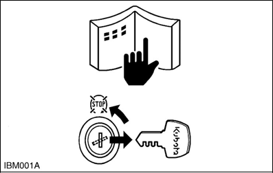
- Stop the engine and remove the key when leaving the operator's seat for cleaning, maintenance, and servicing.
- Before working, remove the negative (-) terminal from the battery or turn off the battery isolator switch.
- Whenever a special tool is required, use the special tool that Kubota recommends.
- Use genuine Kubota parts to ensure safety and machine performance.

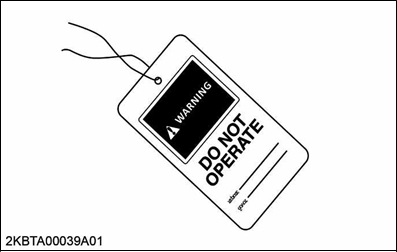
- Hang a DO NOT OPERATE tag near the operator's seat.
- Observe workplace safety rules when performing service and work.

- Tightening bolts and nuts
- Tighten the bolts and nuts to their specified torque.
NOTE- Tighten the bolts and nuts alternately from top to bottom and left to right so the torque is distributed evenly.
- Gradually tighten the bolts and nuts two orthree times.

- Alternately
- Diagonally
- Diagonally from center to outside

- Applying thread-locking fluid
- Clean and dry the location where a thread-locking fluid will be applied with a solvent to remove moisture, oil, and dirt.
- Apply the thread-locking fluid to the tip of the bolt.
- If the threads are large, apply the thread-locking fluid all around the bolt hole.

- Bolt hole (bolts, nuts)
- Screw hole
- Installing circlips
- When installing the circlip, assemble the circlip's angular side (3) toward the side that receives force (4) as shown in the figure.

- Circlip
- Rounded side
- Angular side

- Side that receives force
- Force
- When installing the circlip, assemble the circlip's angular side (3) toward the side that receives force (4) as shown in the figure.


- External circlip
- Internal circlip
- Installing spring pins
- When installing the spring pin, assemble the slit of the spring pin in the direction that receives force as shown in the figure.

- Parallel movement
- Rotational movement
- When installing the spring pin, assemble the slit of the spring pin in the direction that receives force as shown in the figure.
- Handling split pin
- Bend the split pin as shown in the figure to prevent it from coming off.
- Tighten a grooved nut to the specified torque, align the hole of the split pin to the tighten direction and use an S-shaped split.

- Single side split
- Double side split
- S-shaped split
- Handling chain joint and split pin


- Assemble the chain joint with its opening facing the opposite direction of travel.
- Assemble the split pin with its opening facing the direction of travel.

- Chain joint
- Split pin

- Direction of chain moving
- Handling liquid gasket
- Use the specified liquid gasket.
- When using liquid gasket, fully remove the old gasket and grease or oil.
- When applying liquid gasket, apply it on the joint surface with a thickness of 3.0 to 5.0 mm (0.12 to 0.13 in.) without making any gaps.
- When applying liquid gasket near the bolt hole (2), apply it in the inner side.
- If there is a risk of oil leakage or if the hole goes all the way through when applying liquid gasket near the dowel pin (3) hole, apply it in the inner side. If there is no concern of oil leakage, apply it on the outer side.
- Reassemble within 15 minutes after applying; wait for 30 minutes or more then fill with oil.

- Application route
- Bolt hole
- Dowel pin

- Correct
- Incorrect
- 3.0 to 3.5 mm (0.12 to 0.13 in.)
- 3.0 to 5.0 mm (0.12 to 0.19 in.)
- Replacing O-rings
- Remove the burr and clean the O-ring groove.
- Lubricate the O-ring. Do not apply any grease to the floating seal.
- Put the O-ring in the groove.
NOTE- Do not twist the O-ring.
- Remove the burr to avoid damage on the Oring caused by the burr.

- O-ring groove
- O-ring
- Burr

- Replacing oil seals
- Do not face the lip of the oil seal in the wrong direction. Face the seal lip toward the material to be sealed.
- Use a press to install the oil seal until firmly fixed to the boss.
NOTE
In cases when installing an oil seal without a press, place a wooden board on the seal and gently tap the board with a hammer; install the oil seal straightly and evenly. - Grease the seal lip and dust lip.
NOTE- If the seal has a dust lip, grease the gap between the lips.
- After oil seals are replaced, grease the moving parts around the lip to prevent the dry surfaces from wearing against each other during engine start up.

- Packing
- Metal ring
- Spring
- Seal lip
- Grease
- Dust lip

- Air side
- Oil side
- Replacing floating seals
- Apply oil appropriately to both sides of the O-ring and the contact surface.
- Do not twist the O-ring when installing the floating seal.
- Apply oil thinly to the sliding surfaces.
- Install the floating seal in parallel to the sliding surfaces, O-rings, and housings.
- After installation, rotate the floating seal for 3 times to make an oil film on the sliding surface.

- Sliding surface
- O-ring
- Connecting hydraulic hoses
- Clean the inside of the hose fittings.
- Tighten with the specified torque.
- Apply pressure on the hydraulic hose to check for oil leakage.
- Wrapping thread seal tape
- Wrap the thread seal tape around the taper threads two or three turns.
- Tighten the taper thread with the specified torque.
NOTE

- Do not loosen the taper thread after tightening to avoid oil leakage.
- Do not wrap the thread seal tape on the first and second threads to avoid contamination in the hydraulic circuit.

- Thread seal tape
- Male thread
- Female thread
- Clearance
- First and second threads from the screw tip

- Installing elbows with male seat
- Clean the male seat surface and seal.
- Loosen the lock-nut until the top end.
- Install and tighten the elbow by hand until the male seat touches the material surface.

- Lock-nut
- Seat
- Seal
- Adjust the direction of the elbow.
NOTE
Do not loosen to more than one turn.


- Tighten the lock-nut with the specified torque.
NOTE- Check for oil leakage.

- Check for oil leakage.

- Wrench
- Hose
- Torque wrench
- Connecting and disconnecting quick hose couplings
- Push the metal fittings in the direction of the arrow mark.

- Plastic part
- Metal fitting
- Pull the plastic part in the opposite direction of the arrow mark.
- Disconnect the quick hose coupling.
- Push the quick hose coupling in the direction of the arrow mark to connect.
- Make sure that the hose is installed correctly.
- Push the metal fittings in the direction of the arrow mark.
- Handling the battery
![]()

- When removing battery cables, disconnect negative (-) terminal first.
- When installing battery cables, connect positive (+) terminal first.
- Do not install any battery with a capacity (Ah) other than is specified.
- Securely attach the terminal covers on the cables when connecting the cables to the battery terminal posts. There is a danger of short-circuiting if the tip of the cables attached to the battery terminal post is exposed.
- Do not allow dirt and dust to collect on the battery.
- Connect the battery terminals after removing dust, old grease, blue rust and others.
- Apply conductive grease thinly to the battery terminal posts to prevent corrosion.

- Battery negative (-) terminal
- Battery positive (+) terminal

- Handling wire harness
![]()
- Do not let an unprotected wire harness to come in contact with other components.
- Do not clamp the wire harness to fuel hoses.
- If the wire harness is damaged, replace it immediately with a new one.
- Do not alter the electrical device and wire harness.
- Tighten the electrical terminals securely.


- Good
- Bad: Loose bolt
- Check the electrical terminal protection and clamping conditions before connecting the battery cable.

- Covered completely with a protection cover
- Keep the wire harness away from hazardous positions such as rotating parts or high-temperature sections.

- Hazardous position
- Wiring position: bad
- Wiring position: good
- Hazardous position
- If wire harness is damaged or degraded, replace immediately.

- Damaged
- Torn
- Install the grommet securely.

- Grommet


- Good
- Bad: poor installation
- Clamp the wire harness securely. Do not damage the wire harness by the clamp.
- Clamp the wire harness correctly. Do not slack, twist, and pull.

- Wire harness
- Clamp
- Do not pinch the wire harness when installing parts.

- Wire harness


- Bad
- Handling fuses
- Always use fuses of the specified capacity.
- Do not use steel or copper wiring instead of fuse.
- Do not install work light or radio without auxiliary power line.
- Do not install auxiliaries to the fuses. The fuses may blow.

- Fuse
- Fusible link
- Slow blow fuse

- Handling connectors
- When disconnecting the locking connectors, be sure to disengage the lock before disconnecting. There are two kinds of locks: one requires pressing and the other requires pulling.

- Press
- Hold on tightly to the connectors when disconnecting them.
- Do not pull wire harness itself.

- Correct method
- Incorrect method
- Make sure the terminal condition of the connectors is not bent, rusty, and so on.
- If the terminal is rusted, remove rust with sandpaper.
However, do not polish the terminal of the waterproof connector or the plated terminal.

- Missing terminal
- Bent terminal
- Sandpaper
- Rust
- Cover the female bullet terminals and male bullet terminals securely with the plastic covers.
- Make sure that the bullet terminals are secure and connected securely to the tip.

- Good
- Bad: damaged cover
- Bad: poor connection


- Cover the female connectors and male connectors securely with the plastic covers.

- Cover

- Good
- Bad: damaged cover
- Wiring color
- Wire colors are specified in the color codes.

- Wire color
- Stripe

| Wiring Colors | Color code |
| Black | B |
| Brown | BR, Br |
| Green | G |
| Gray | GY, GR, Gr |
| Blue | L |
| Light green | LG, Lg |
| Orange | OR, Or |
| Pink | P |
| Purple | PU, Pu, V |
| Red | R |
| Sky blue | SB, Sb |
| White | W |
| Yellow | Y |
- This symbol of "/" shows color with stripe(s).
(An example)
W/R:
White with red stripe
- Washing the machine with a high pressure washer
Use a high pressure washer properly to avoid personal injuries and damages to the machine.
![]()
- Damaged or cut the wire harness may cause fire.
- Damaged hydraulic hoses or oil seals may cause injury due to hydraulic oil gushing out.
![]()
- Water infiltration may cause machine problems.
- Adjust the high pressure washer nozzle for a wide spray. Do not adjust to pencil point spray.
- Spray the water at least 2 m away from the machine.
SAFETY
SAFETY FIRST
This symbol, the industry's "Safety Alert Symbol", is used throughout this manual and on labels on the machine itself to warn of the possibility of personal injury. Read these instructions carefully. It is essential that you read the instructions and safety regulations before you attempt to assemble or use this unit.

|

|

|

- Indicates that equipment or property damage could result if instructions are not followed.
NOTE
- Gives helpful information.
- Working precautions
![]()
- Understand all safety instructions and safety labels in this manual.
- Park the machine on a stable and level ground then lower the attachment to check the machine safely.
- Stop the engine and remove the key when leaving the operator's seat for cleaning, maintenance, and servicing.
![]()
- Hang a DO NOT OPERATE tag near the operator's seat.
- Do not use worn or cracked tools. Use tools in a proper way with enough strength.
- In regards to the facility which is used in the workshop, follow each safety instruction.
- Preparing for emergencies
![]()
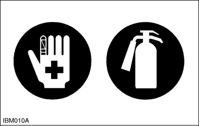
- Keep a first aid kit and fire extinguisher ready at all times.
- Keep emergency numbers near your telephone at all times.
- Working cautions
![]()
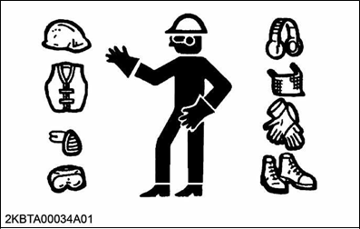
- Wear proper service attire when performing work. Do not wear loose clothing as they could get caught on machine components.
- Wear the proper protective equipment when working around the machine. For example helmet, eye protector and protective shoes.
- Do not work around the machine if you are tired or have consumed alcohol or drugs.
![]()
- Keep the machine away from obstacles and hazardous materials.
- Ensure the working environment is properly ventilated.
- Do not allow third parties to come near the machine.
![]()
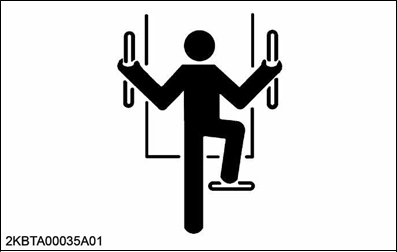
- Make sure you have the support of the 3 points with both hands holding the handle and one foot at the step when getting on and off the machine.
- When working under the machine, make sure the machine does not move back and forth or side-toside.
- When working under the machine, provide secure support for the machine.
- When using a hydraulic jack, always use with a rigid rack to prevent the machine from falling.
- Starting machine safely
![]()
- Do not do the following work when starting the engine.
- Short across starter terminals.
- Bypass the safety start switch.
- Make sure there are no bystanders or obstacles present around the machine before starting the engine.
- Do not start the engine unless the operator is seated in the operator's seat.
- Make sure that the pilot levers are in neutral before starting the engine.
![]()
- Lock the covers before starting the machine.
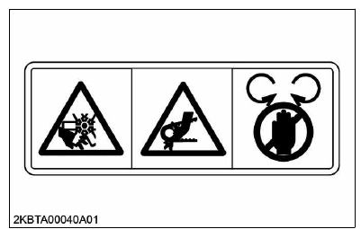
- Keep away from rotating and moving objects.
- Keep tools and waste cloth away from rotating and moving objects.
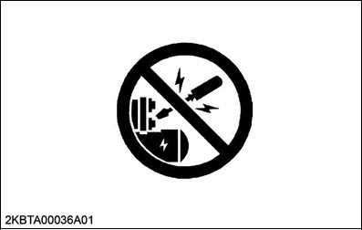
- Preventing fires
![]()
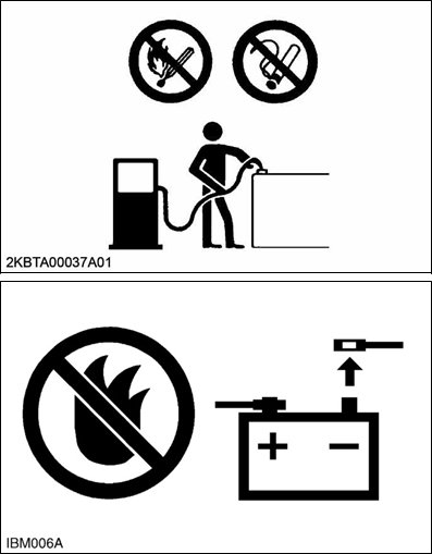
- Keep fire (welding sparks, grinding sparks, cigarettes) away from the fuel.
- Wipe the fuel off when spilled.
- Keep fire (welding sparks, grinding sparks, cigarettes) away from the battery. The battery produces oxygen and hydrogen gas that are flammable.
- Disconnect the negative (-) terminal first when disconnecting the battery cable.
- Connect the positive (+) terminal first when connecting the battery cable.
- Do not short circuit the machine.
- Do not splash the hydraulic oil on the exhaust components.
- Preventing acid burns
![]()
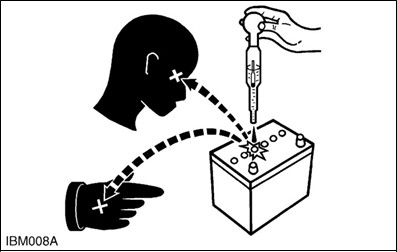
- Keep the electrolyte away from your eyes, hands, and clothes. Sulfuric acid in the battery electrolyte is poisonous: it can cause blindness and is strong enough to burn your skin and clothing. If you spill electrolyte on yourself, clean yourself with water and get a medical aid immediately.
- Avoiding high pressure fluid
![]()
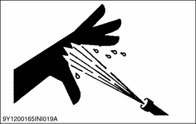
- Keep away from high pressure fluids bursting from a hose or pipe. The fluid can penetrate your skin and cause serious injuries.
- Get a medical aid immediately if an accident occurs.
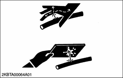
![]()
- Release residual pressure in the hydraulic circuit before removing the hydraulic components.
- Pay attention when releasing pressure in hydraulic circuit, because the machine or attachment might move unexpectedly.
- Check the coolant temperature and release the pressure before opening the radiator cap.
- Avoiding hot exhaust
![]()
- Avoid skin exposure and contact with hot exhaust gas or components.
- Exhaust gas and components are extremely hot during operation.
![]()
- Do not work immediately after stopping the engine. The engine, muffler, radiator, and hydraulic components are extremely hot.
- Do not remove caps and plugs soon after stopping the engine. The temperature and pressure of the coolant, hydraulic oil, and fuel are still high.
- Cleaning exhaust filter
![]()
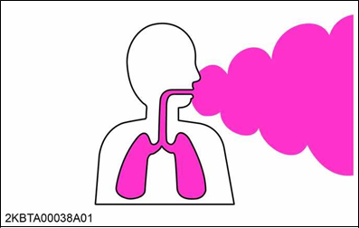
- Avoid skin exposure and contact with hot exhaust gas or components. Exhaust gas and components are extremely hot during regeneration of the diesel particulate filter (DPF).
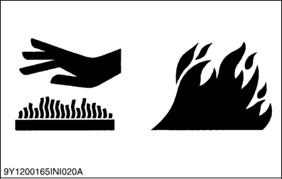
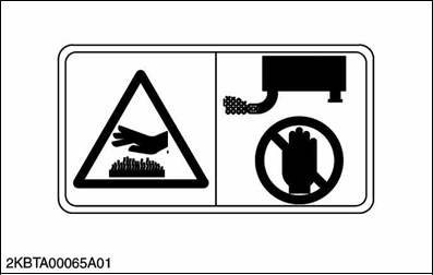
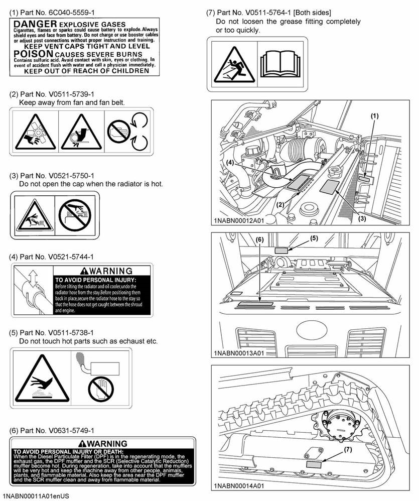
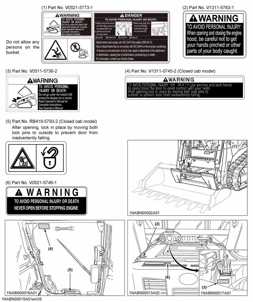
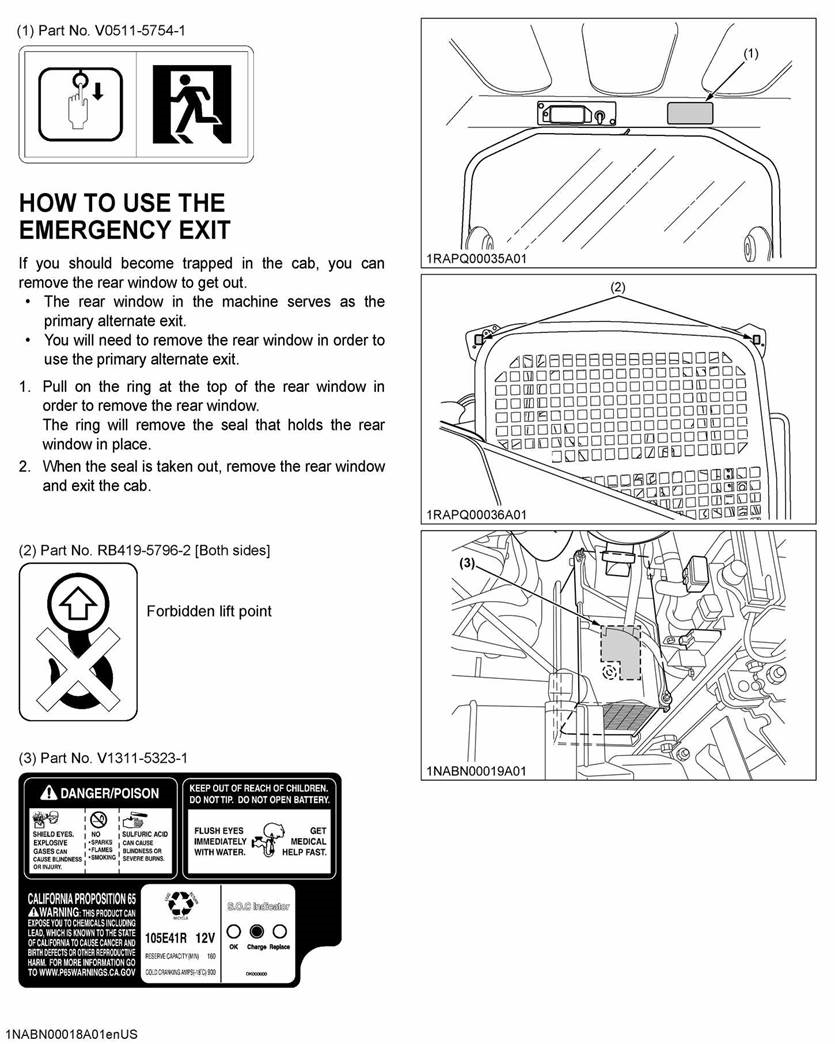
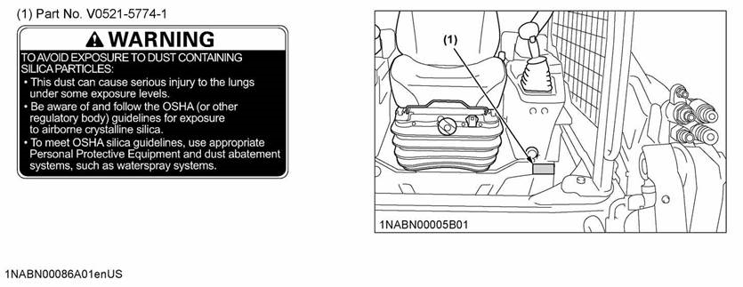
SAFETY LABELS
- Safety labels placement
Read the safety instructions on safety labels carefully to avoid personal injury.
![]()
![]()
![]()
![]()
![]()
![]()
- Safety labels maintenance
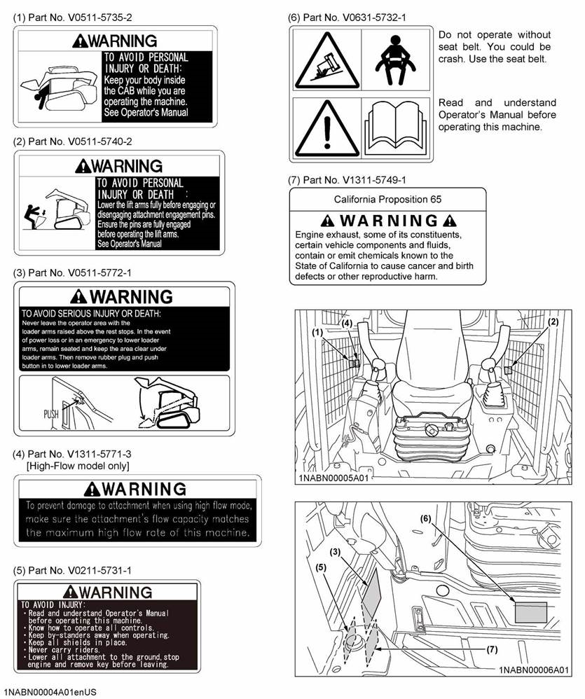
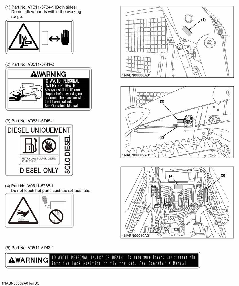
- Keep safety labels clean and free from obstructing material.
- Clean safety labels with soap and water, dry with a soft cloth.
- Replace damaged or missing safety labels with new safety labels from your KUBOTA dealer.
- If a component with safety label(s) affixed is replaced with new part, make sure that new safety label(s) is (are) attached in the same location(s) as the replaced component.
- Mount new safety labels by applying on a clean, dry surface and pressing any bubbles to outside edge.
Documents / ResourcesDownload manual
Here you can download full pdf version of manual, it may contain additional safety instructions, warranty information, FCC rules, etc.
Advertisement


Need help?
Do you have a question about the WSM SVL97-2 and is the answer not in the manual?
Questions and answers