
Subscribe to Our Youtube Channel
Related Manuals for Kubota RA2072


Summary of Contents for Kubota RA2072
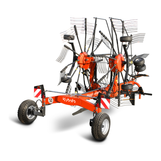
- Page 1 RA2072 RA2072 Hydro Operator’s manual Original operator’s manual Edition 04.2015 Date of print 06.2015 Language EN-US Machine number VF69670236 – Model VF6967 Document number VF16662027.EN-US...
- Page 2 In order for your dealer to assist you as efficiently as possible, you will need to provide some information about your machine. Please enter the details here. Designation RA2072 RA2072 Hydro Operating width 6.20 - 7.30 m (20.30 - 23.95 ft)
-
Page 3: Table Of Contents
Table of contents Table of contents Preface ............Preparations on the field ......Target group for Safety this operator’s manual General Symbols used Lowering the machine Safety ............Operation ........... For your safety Safety DANGER, WARNING and CAUTION labels General Crop processing Who is allowed to... - Page 4 Table of contents EC Directive 2006/42/EC Index ............
-
Page 5: Preface
Preface Target group for Preface WARNING this operator’s manual Simplified illustrations for better understanding Illustrations of the machine in the operator’s manual are shown without protective equipment – or with the protective equipment open – for better understanding. Be sure to observe the safety information and follow the handling instructions in the operator’s manual. -
Page 6: Symbols Used
Preface Symbols used In this operator’s manual, the following symbols and terms have been used: • A bullet point accompanies each item in a list. A triangle indicates operating functions which must be performed. An arrow indicates a cross-reference to other sections of this manual. - Page 7 Preface...
-
Page 8: Safety
Safety Safety California Proposition 65 WARNING Engine exhaust, some of its constituents, certain machine components and fluids, contain or emit chemicals known to the State of California to cause cancer and birth defects or other repro- ductive harm. SAFETY FIRST This symbol, the industry's "Safety Alert Symbol", is used throughout this manual and on labels on the machine itself to warn of the possibility of personal injury. -
Page 9: For Your Safety
Safety For your safety Know your equipment and it's limitations. Read this entire manual before attempting start and operate the units. This chapter contains general safety instructions. Each chapter of the operator’s manual contains additional specific safety information which is not described here. Observe the safety information: •... -
Page 10: Danger, Warning And Caution Labels
Safety DANGER, Safety-related stickers attached to the machine indicate potential hazards. The stickers must not be removed. Illegible or missing WARNING and stickers should be replaced. You can obtain new stickers as CAUTION labels replacement parts from your dealer. DANGER, WARNING and CAUTION labels on the machine... -
Page 11: Danger, Warning And Caution Labels
Safety Meaning of DANGER, WARNING and CAUTION labels... - Page 12 Safety Inner tube. Outer tube.
- Page 13 Safety Lubrication points Hidden lubrication points are marked with an information label. Lubricate the machine in accordance with the instructions in the "Maintenance" chapter.
- Page 14 Safety Signalling equipment On the machine there are signalling equipment, signs and stickers that serve to ensure safety in road traffic. The signalling equipment must – USA be in good working order at all times. The signs and stickers must not be removed.
- Page 15 Safety Signs Additional markings are required for road transport in some U.S. states and some Canadian provinces: Marking for slow-moving vehicle – SMV This SMV emblem shall be used on all slow moving machines when operated or traveling on public roads. •...
-
Page 16: Operate The Machine
Safety Who is allowed to Qualified machine operators Only qualified persons who have been informed of the dangers operate the associated with handling the machine are permitted to operate, machine? service or repair the machine. The necessary knowledge can be gained in the course of agricultural vocational training, professional training or intensive instruction. - Page 17 Safety No persons in the working area Ensure that no persons are present in the slewing and working area of the machine. Persons could be caught by the machine within this area. This could result in fatal injury. Proper working condition Ensure that the tractor and the machine are always in proper working condition.
- Page 18 Safety Never work on the machine while it is running No operations may be performed on the machine while it is running. Objects or persons can be caught, drawn in or crushed. Serious or fatal injury may be caused as a result. PTO shaft Use only the PTO shafts specified by the manufacturer and read the attached operator’s manual carefully.
-
Page 19: Coupling
Safety Coupling Increased risk of injury When the machine is being coupled to the tractor, there is an increased risk of injury. Therefore: • Shut off the engine, set the parking brake, remove the ignition key and secure the tractor against rolling away. •... -
Page 20: Road Transport
Safety Road transport Ensuring road safety The machine must conform to current national traffic regulations if you intend to drive it on public roads. Ensure the following: • Lighting, warning and protective equipment must be fitted. • The permissible transport widths and weights, axle loads, tire load- bearing capacities, laden weights and national speed restrictions must be observed. - Page 21 Safety Speed adjustment In poor road conditions and at high speeds, significant forces can be generated which subject the tractor and machine material to high or excessive stresses. Adjust your driving speed to the road conditions. A driving style which is not adapted to conditions can cause accidents. Accidents with serious or fatal injuries may be caused as a result.
-
Page 22: Operation
Safety Operation Ensure that the machine is in proper working condition Do not operate the machine unless it is in proper working condition. Check all key components and their correct operation before use. Replace defective components. Defective components can cause material damage and personal injury. -
Page 23: Uncoupling
Safety Uncoupling Increased risk of injury There is an increased risk of injury when uncoupling the machine from the tractor. Therefore: • Shut off the engine, set the parking brake, remove the ignition key and secure the tractor against rolling away. •... -
Page 24: Care And Maintenance
Safety Care and Observe the care and maintenance intervals Observe the periods specified in the operator’s manual for recurrent maintenance checks and inspections. If these periods are not observed, damage to the machine and accidents may be caused as a result. Use original parts Many components have special properties that are essential for the stability and correct operation of the machine. -
Page 25: Further Regulations
Safety Further Observe the regulations In addition to the safety information listed above, please observe the regulations following: • Accident prevention regulations in your local area. • Generally recognised safety regulations, occupational health requirements and road traffic regulations. • The instructions provided in this operator’s manual. •... -
Page 26: Getting To Know The Machine
Getting to know the machine Range of This product is classified as replaceable equipment in accordance Getting to know the machine with EC directive 2006/42/EC and agricultural implement in application accordance with ASABE S390. The machine is a twin rotor rake, which is suitable only for the raking together of mown, stalked material (for example, hay or straw). -
Page 27: Designation Of Components
Getting to know the machine Designation of components Rotor gear Transport chassis Deflector bar Tine supports Tines Swath former Main frame Attachment carrier Sustainer Drive Front deflector bar Rotor chassis Tine guard stowage compartment... -
Page 28: Technical Specifications
Getting to know the machine Technical specifications Dimensions in transport position Standard With hydraulic transport transport chassis [m] chassis [m] 5.90 (16.36 ft) 5.90 - 6.06** Length (16.36 ft - 21.65 ft) 3.65 ** - 3.90 3.44** - 3.90 Height with all tine supports (11.76 ft - 12.80 ft) (11.29 ft - 12.80 ft) Width at transport wheels... - Page 29 Getting to know the machine Standard With hydraulic transport Dimensions in work position transport chassis [m] chassis [m] Length 5.90 (16.36 ft) Height in work position 1.79 (5.88 ft) Working width 6.20 - 7.30 (20.30 - 23.95 ft) Width 6.35 - 7.45 (20.84 ft - 24.45 ft) Distance between the rotors 0.20 - 1.30 (0.66 ft - 4.27 ft)
- Page 30 Getting to know the machine Weights Work position Transport position Total weight 1 640 kg (2 557 lbs) Load supported on parking stand 725 (1 598 lbs) Load supported on lower link 615 (1 356 lbs) Parking stand: 895 (1 973 lbs) Transport chassis axle load Lower link: 1 005 (2 216 lbs) Tractor equipment...
- Page 31 Getting to know the machine Machine equipment Swath deposit Swath former with auto-swivel Standard Rotors / tine supports / tines Number of rotors 11 swaths to the left Number of tine supports per rotor 11 swaths to the right Number of tines per tine support Removable Tine supports Standard Tine cover...
-
Page 32: Pilotbox – Hydro Version
Getting to know the machine Pilotbox – Hydro version Protecting electrical parts against moisture The electronic control system, pilotbox and electrical plug connec- tions must be protected against damp and penetrating moisture. Dampness in electronic devices can lead to leakage current, which results in malfunction. -
Page 33: Function Overview
Getting to know the machine Function overview Standard version The table below provides a summary of the functions. Be sure to follow the other instructions and note the safety information in the operating manual. Steering Machine position Function • Single-acting hydraulic control Transport Standard device on the tractor. - Page 34 Getting to know the machine Steering Machine position Function • Single-acting hydraulic control Swathing with right rotor [+] Standard device on the tractor. • The left rotor remains in the head- • land position. Cable-controlled ball valve for • Raise the machine to the headland left rotor.
- Page 35 Getting to know the machine Steering Machine position Function • Crank on right rotor. Working depth of right rotor Standard • Switch off the PTO shaft drive. • Switch off the tractor and secure it. • Set the working depth using the crank on the right rotor.
- Page 36 Getting to know the machine Hydro version The table below provides a summary of the functions. Be sure to follow the other instructions and note the safety information in the operating manual. Steering Machine position Function • Pilotbox switched off. Transport Hydro •...
- Page 37 Getting to know the machine Steering Machine position Function • Pilotbox switched on. Swathing with left rotor [+] Hydro • • Switch the pilotbox on. Select position A on the • Select position A on the pilotbox. pilotbox. • Using the tractor's single-acting hy- draulic control device, raise the right rotor and then lower it.
- Page 38 Getting to know the machine Steering Machine position Function • Pilotbox switched on. Lower the transport chassis [+] Hydro • • Switch the pilotbox on. Select position B on the • Select position B on the pilotbox. pilotbox. • Lower the transport chassis using the tractor's double-acting hydraulic control device.
-
Page 39: Delivery And Assembly
Delivery and assembly Checking the Delivery is in the fully assembled state Delivery and assembly The machine is delivered fully assembled. Using the check list, check scope of delivery the loose parts on delivery. If any parts of the machine have not been fitted or are missing, please contact your dealer. -
Page 40: Checking Tandem Axle [+]
Delivery and assembly Checking WARNING tandem axle [+] Ensure that the tandem axle is positioned correctly Ensure that the tandem axles are positioned correctly. If they are positioned incorrectly, this will cause damage to the machine. Check that the tandem axles [+] are aligned correctly. •... -
Page 41: Length Of Pto Shaft
Delivery and assembly Length of The length of the PTO shaft was selected at the factory to suit almost all types of tractor. Only in exceptional cases is a correction of the PTO PTO shaft shaft length required on individual tractors. Check the length of the PTO shaft on each tractor prior to first use. - Page 42 Delivery and assembly Shortening the PTO shaft Pull the PTO shaft apart and connect one half to the tractor PTO shaft drive and one to the machine and secure them. Place the two shaft halves next to each other and: •...
-
Page 43: Steering
Delivery and assembly Steering The following applies to all instructions below: Please note the following instructions and safety information: »Coupling the machine«. Page 44. »Coupling the lower link«, page 45. »Coupling the PTO shaft«, page 47. Checking the steering WARNING... -
Page 44: Coupling The Machine
Coupling the machine Safety Coupling the machine WARNING Observe the safety information Disregard for safety information can lead to serious or fatal injury. See chapter »Safety«, page 8. Increased risk of injury When the machine is being coupled to the tractor, there is an increased risk of injury. -
Page 45: Coupling The Lower Link
Coupling the machine Coupling the lower link Tractors with quick- release couplings Lower link Catch WARNING Follow the instructions for the quick-release coupling Follow the instructions below for tractors with quick-release couplings. If this requirement is ignored, the consequence may be damage to the machine and even life-threatening injuries. -
Page 46: Swivelling In The Parking Stand
Coupling the machine Swivelling in the parking stand After coupling the machine to the tractor, raise and secure the parking stand. Shut off the engine, set the parking brake, remove the ignition key and secure the tractor against rolling away. ... -
Page 47: Coupling The Pto Shaft
Coupling the machine Coupling the Make sure that you fit the PTO shaft in the correct installation position. There is a marking on the guard tube of the PTO shaft. PTO shaft WARNING Do not use force When coupling the PTO shaft, do not use a hammer or any similar tools. -
Page 48: Wheel Chocks
Coupling the machine Wheel chocks WARNING Use wheel chocks Never remove the wheel chocks before the machine has been coupled to the tractor. Persons could be run over by the machine or the tractor. Serious or fatal injury would be caused as a result. Wheel chock ... -
Page 49: Connections
Coupling the machine Connections Electrical connections WARNING Checking the electrical cables Check the electrical cables. The electrical cables must not chafe or hang loose. Electrical cables that have been torn away or worn through must be replaced. Damage to the machine may be caused as a result. - Page 50 Coupling the machine Function overview of Check that the lighting equipment is functioning using the following lighting equipment – USA table. Device lights Tractor lights Left amber Left red Right red Right amber Headlight “OFF” — — Headlight “ON” —...
- Page 51 Coupling the machine Pilotbox [+] WARNING Pilotbox Switch off the pilotbox for all tasks on the machine Always switch off the pilotbox when coupling or uncoupling and when carrying out service or maintenance work or any task on the machine. If the pilotbox is switched on and accidentally actuated, unexpected machine movements may be triggered.
- Page 52 Coupling the machine Hydraulic WARNING connections Check hoses and couplings Check all hydraulic hoses for damage before connecting them. Check all hydraulic couplings for firm seating after connecting them. Defective hydraulic hoses and poorly fitting hydraulic connections can trigger unanticipated movements in the machine, causing severe damage to the machine as well as personal injury.
- Page 53 Coupling the machine Connecting the WARNING hydraulic couplings Make sure the connection is correct Ensure that the hydraulic system is connected correctly, Otherwise, damage to the machine and personal injury may be caused as a result. Shut off the engine, set the parking brake, remove the ignition key and secure the tractor against rolling away.
- Page 54 Coupling the machine Hydro version The rotors are raised and lowered via the single-acting hydraulic control device. Single swath operation is controlled by switching on and actuating the pilotbox. The swath width is controlled using the double-acting hydraulic control device. Raising and lowering the transport chassis is controlled by switching on and actuating the pilotbox.
-
Page 55: Preparing For Use
Preparing for use Safety Preparing for use WARNING Observe the safety information Disregard for safety information can lead to serious or fatal injury. See chapter »Safety«, page 8. Securing the machine Secure the machine against unintentional starting and rolling away. Use wheel chocks. The machine must stand on a level, firm and secure surface and be supported during the work, if necessary. -
Page 56: General
Preparing for use General The following applies when performing all adjustment work: Check the tire pressure. Secure the machine. Lower the machine to the work position. Undo the appropriate bolts. Make the required adjustment. Retighten the bolts. ... -
Page 57: Frame Pitch
Preparing for use Frame pitch For improved pick-up of the crop, use the three-point power lift system to incline the main frame approx. 1° further to the front. 1° Use the three-point power lift system to incline the main frame approx. - Page 58 Preparing for use Adjusting the rotor Before carrying out any adjustment work, you must secure the machine: pitch Move the machine to the headland position using the tractor's control device. Close the ball valve. Shut off the engine, set the parking brake, remove the ignition key and secure the tractor against rolling away ...
- Page 59 Preparing for use Adjust the rotor pitch for a single axle Loosen the M 20 nut. Remove the M 20 nut and washer. Remove the wheel. Fit the wheel in the desired position. Put the washer and M 20 nut back on. ...
- Page 60 Preparing for use Adjust the rotor pitch for a tandem axle [+] Remove the M 20 nut. Remove the tandem axle. Securing pin Fit the tandem axle in the desired position. Fit the securing pin in the opposite hole. ...
-
Page 61: Working Depth
Preparing for use Working depth WARNING Never set the tines too deep If the tines are set too deep: • The tines are overstressed. • The tines will soil the crop. Tines • This can result in damage to the machine. Adjust the working depth as follows: Working depth ... -
Page 62: Road Transport
Road transport Safety Before transporting the machine on public roads, please read the Road transport following safety information. Compliance is mandatory and will help you to avoid accidents. WARNING Observe the safety information Observe the safety information. Disregard for safety information can lead to serious or fatal injury. -
Page 63: General
Road transport General The following work steps are described in this section: • »Prior to road transport« • »Folding in the guard bars« • »Folding the machine into the transport position« • »Checking the machine« Prior to road When driving on public roads, the machine must be in the transport position. - Page 64 Road transport Setting the lowest Move the machine to the headland position using the tractor's single-acting hydraulic control device. transport height Adjust the swath to the smallest width using the tractor‘s double- acting hydraulic control device. Hydro version ...
- Page 65 Road transport Folding the machine WARNING into the transport position No persons within the folding range No persons may be present within the folding range and working area. Persons can be trapped by the machine. Serious or fatal injury may be caused as a result. Ensure that hydraulic connections are correct Before slewing, always check that the hydraulics for the slewing device are correctly connected to a double-acting control valve.
- Page 66 Road transport Attaching the tine cover WARNING Exercise caution when close to unprotected tines Maintain a sufficiently safe distance from exposed tines. When working in the vicinity of the tines, ensure that you have a firm footing (risk of slipping on wet ground). Otherwise, serious or fatal injury may be caused as a result.
-
Page 67: Road Transport
Road transport Road transport WARNING Follow the instructions below for road transport. This could cause traffic accidents and other accidents with fatal conse- quences. Before pulling away, check the immediate vicinity. Always make sure that you have a clear field of vision and, in particular, look out for children within the operating area of the machine. -
Page 68: Preparations On The Field
Preparations on the field Safety The following applies for all preparations on the field: Preparations on the field WARNING Observe the safety information Disregard for safety information can lead to serious or fatal injury. See chapter »Safety«, page 8. Switch off the tractor and secure it Before you dismount: ... -
Page 69: General
Preparations on the field General The following work steps are described in this section: • »Lowering the machine« • »Folding out the guard bars« • »Adjusting the swath former« Lowering the After road transport, the machine is brought into the work position on the field. - Page 70 Preparations on the field Lowering the machine in work position Place the machine onto that is as flat as possible before changing from work to transport position. Switch on the tractor. Use the tractor’s single-acting hydraulic control device to release the lifting arm locking mechanism.
- Page 71 Preparations on the field Folding out the guard bars After the tines have been attached, all protective devices must be moved from transport to work position. Latch for transport position Latch for work Fold out the guard bar as follows: position ...
- Page 72 Preparations on the field Adjusting the swath The swath former is folded into the correct position when changing from the transport to the work position. former Adjusting the swath former in relation to the direction of travel It is possible to adjust the direction of travel of the swath former as follows: ...
-
Page 73: Operation
Operation Safety Operation WARNING Observe the safety information Disregard for safety information can lead to serious or fatal injury. See chapter »Safety«, page 8. No riding on the machine Persons or objects must never be transported on the machine. Carrying passengers, especially children, on the machine is life threatening and prohibited. -
Page 74: General
Operation General The following work steps are described in this section: • »Crop processing« • »Twin rotor operation« • »Single rotor operation with hydraulic single lift [+]« • »Adjusting the swath width« • »Driving on headlands« Suitable working speeds Select a driving speed (approx. 4 to 12 km/h) at which the crop is picked up cleanly and completely. -
Page 75: Using The Machine
Operation Using the machine WARNING No persons in the working area Ensure that no persons, especially children, are present in the slewing and working area of the machine. Persons could be caught by the machine within this area. This could result in fatal injury. - Page 76 Operation Twin rotor operation Central swath with two rotors WARNING Distance from the rotor Maintain a safe distance from the rotor when it is rotating. Nobody may remain in close proximity to the machine when rakes and swathers are running. Otherwise, serious or fatal injury may be caused as a result.
- Page 77 Operation Single rotor WARNING operation with hydraulic Distance from the rotor Maintain a safe distance from the rotor when it is rotating. Nobody single lift [+] may remain in close proximity to the machine when rakes and swathers are running. Otherwise, serious or fatal injury may be caused as a result.
- Page 78 Operation Single rotor WARNING operation with active rotor Switch off the tractor and secure it Shut off the engine, set the parking brake, remove the ignition key and secure the tractor against rolling away. An unsecured tractor can run you over or trap you. Serious or fatal injury may be caused as a result.
- Page 79 Operation Single swath with right rotor in transport position The inactive side shaft is removed. See »Remove the side shaft«, page 78. Move the machine to the transport position using the tractor's single-acting control device. Pull the rope on the right rope-controlled ball valve once. ...
- Page 80 Operation Single rotor operation with WARNING Hydro version [+] Distance from the rotor Maintain a safe distance from the rotor when it is rotating. Nobody may remain in close proximity to the machine when rakes and swathers are running. Otherwise, serious or fatal injury may be caused as a result.
-
Page 81: Working Speed
Operation Working speed WARNING Prevent crossing swathes As a general measure, prevent the crossing of mowing swathes. The crop is distributed unevenly and the machine is subjected to abrupt stresses. Damage to the machine may be caused as a result. Allow ample space when driving around obstacles Obstacles must be circumnavigated in good time and at a distance. -
Page 82: Driving On Headlands
Operation Driving on headlands WARNING Observe the contour of the terrain Pay even more attention when driving on an incline. Avoid inclines on which the combination (tractor and machine) could slip or overturn. There is an increased risk of tipping and injury in a position at right angles to the direction of the slope. -
Page 83: Check List For Operation
Operation Check list for Guard bar folded down? operation All tine supports fitted and secured? Swath former adjusted and secured? All lynch pins secured? Machine set correctly? -
Page 84: Cleaning And Care
Cleaning and care Safety The following applies to all cleaning and care work: Cleaning and care WARNING Observe the safety information Disregard for safety information can lead to serious or fatal injury. See chapter »Safety«, page 8. Securing the machine •... -
Page 85: General
Cleaning and care General The following work steps are described in this section: • »Cleaning« • »Care« Cleaning Switch off the tractor PTO shaft drive. Use the tractor's hydraulic control device to fold the machine into its work position. ... -
Page 86: Parking And Storage
Parking and storage Safety When setting down and parking the machine, special safety Parking and storage precautions have to be observed: WARNING Observe the safety information Disregard for safety information can lead to serious or fatal injury. See chapter »Safety«, page 8. Keep children away from the machine Forbid children from playing on or around the machine. -
Page 87: Uncoupling The Machine
Parking and storage Uncoupling the Uncoupling the machine is carried out in the reverse order to coupling the machine to the tractor. Proceed as follows: machine Chapter »Coupling the lower link«, page 45. Bring the machine into the transport position. Parking pockets ... -
Page 88: Maintenance
Maintenance Safety The following applies to all maintenance work: Maintenance WARNING Observe the safety information Disregard for safety information can lead to serious or fatal injury. See chapter »Safety«, page 8. Requirements for maintenance work Only perform the maintenance work if you have the required expert knowledge and suitable tools. -
Page 89: General
Maintenance Protective measures Additives in oils and lubricants may have adverse effects on health. As marking in accordance with the hazardous goods regulation is not when handling oils or necessary, please always ensure the following: lubricants WARNING Avoiding skin contact Avoid skin contact with these materials. - Page 90 Lubricant Gear Oil and Grease used on this machine has to meet the following requirements: Lubricant Specifications Gear oil SAE 90 API-GL-4 or 5 e.g.: KUBOTA HEAVY DUTY 80W-90 GEAR OIL Grease NLGI GC/LB e.g.: KUBOTA Polyurea Grease...
- Page 91 Maintenance Maintenance intervals General ● ● ● All bolts ● ● ● Visual inspection ● ● ● Bearing ● ● Hose connections ● ● ● Air pressure ● ● ● Lighting equipment Hydraulics ● ● ● Hydraulic hoses every 6 years ●...
-
Page 92: Screwed Connections
Maintenance Screwed WARNING connections Use original parts Machine components have special properties that are essential for the stability and correct operation of the machine. Only spare parts and accessories supplied by the manufacturer have been tested and approved. Other products may adversely affect the correct operation of the machine and safety. - Page 93 Maintenance Special tightening Observe the special tightening torques for the following screwed con- nections: torques • 210 Nm Ripp screw M 14 rotor gear. 210 Nm ripp screw M 14 • 90 Nm (66.38 ft.lbs) spring tine. 90 Nm Spring tines •...
-
Page 94: Lubrication Points For Grease
Maintenance Lubrication points Working with a grease gun Before applying the grease gun for grease • Clean grease fittings on the machine and gun fittings on the grease gun. Lubricate the bearings with one or two presses of the grease gun. If you feel resistance at the second press, do not press a second time. -
Page 95: Lubricating The Pto Shafts
Maintenance Lubricating the The PTO shaft manufacturer's own operator’s manual is included with each PTO shaft. This includes detailed information on the relevant PTO shafts version of the PTO shaft. WARNING Check the guard components Check all guard components of the PTO shafts for wear or damage (visual inspection). -
Page 96: Filling Quantities
Maintenance Filling quantities CAUTION Observe the correct fill quantities Observe the correct lubricant fill quantities. Check them regularly. A lubricant level which is too low or too high may result in damage to the machine. Gear box Oil volume Angular gear 1.0 l (1.06 US qt) Rotor gear, left 6.2 l (6.55 US qt) -
Page 97: Hydraulics
Maintenance Hydraulics WARNING Hydraulic system at zero pressure Work must only be performed on the hydraulic system if the tractor and machine hydraulic system is at zero pressure. A pressurised hydraulic system can trigger unforeseen movements on the machine and can cause serious machine damage and personal injury. -
Page 98: Checking Sliding Elements
Maintenance Checking sliding elements The sliding elements on the two main lifting arms ensure smooth and even running of the inner lifting arms. The sliding elements must be checked on a regular basis, and readjusted and lubricated if necessary. Check that the telescopic arms retract and extend correctly in the headland position. - Page 99 Maintenance Checking WARNING the track Never carry out work on the steering Contact your dealer if specifications differ. Never carry out any work on the steering or tracking yourself. This can result in traffic accidents and accidents causing serious or fatal injuries. If the machine rolls at an offset angle to the tractor when driving a Steering arm straight line, the directional stability is set incorrectly.
-
Page 100: Accessories
Accessories Optional additional equipment does not form part of the standard Accessories scope of delivery, and, in this manual, is indicated by a plus symbol [+]. Additional equipment is available to order from your dealer. Tine saver For a good swath deposit, both tine legs must run parallel to one another. -
Page 101: Tandem Axles
Accessories Tandem axles The optional tandem axles make for better contours. • Note: The wide track is in front. The tandem axles replace the rear running wheels of the rotor chassis. Separate assembly instructions are supplied. Spare wheel The optional spare wheel is fitted to the guard bar of the machine. The spare wheel is fitted to the machine's guard bar. -
Page 102: Fault Elimination
Fault elimination Troubleshooting Faults can often be eliminated quickly and easily. Before contacting Fault elimination Customer Service, refer to the table to check whether you can remedy the fault yourself. WARNING In case of a fault, proceed as follows: Immediately stop operation. •... - Page 103 Fault elimination Problem Cause Solution Poor adaptation to the Please consult your dealer. You will find Rotor not working cleanly. contours of the land due to assistance under »Circuit diagrams«, severe rotor load relief page 105. Inner lifting arms have stiff and Sliding elements wrongly Adjust sliding elements correctly.
-
Page 104: Emergency Manual Function
Fault elimination Emergency manual function A defective solenoid valve can be switched manually. Do not continue working. Fold the machine to the transport position in order to replace Hydraulic chassis solenoid valve the defective valve. Switch off the pilotbox. ... -
Page 105: Circuit Diagrams
Circuit diagrams Hydraulic circuit Circuit diagrams diagram Standard version Lift arm extension Left lift arm Right lift arm Cable-controlled ball valve for hydraulic individual lift [+] Tractor hydraulics... - Page 106 Circuit diagrams Hydro version Lift arm extension Left lift arm Right lift arm Hydraulic chassis Tractor hydraulics...
-
Page 107: Pilotbox Circuit Diagram
Circuit diagrams Pilotbox circuit diagram On/Off switch Preselection switch Control light Hydraulic valves A, B, C... -
Page 108: Lighting Equipment Circuit Diagram – Usa
Circuit diagrams Lighting equipment circuit diagram – USA... -
Page 109: Decommissioning
Decommissioning Disposal During decommissioning, the individual parts must be disposed of Decommissioning properly and in an environmentally friendly manner. Please observe the waste disposal guidelines that are currently in force. Plastic parts Plastic parts can be disposed of in normal household waste (residual waste), depending on the laws specific to your country. -
Page 110: Ec Declaration Of Conformity
EC Declaration of Conformity Conforms to EC Declaration of Conformity EC Directive Kverneland Group Kerteminde AS 2006/42/EC Taarupstrandvej 25 DK-5300 Kerteminde Denmark declare with sole responsibility that the product SwatMaster 7242, 7242 Hydro Andex 724, 724 Hydro 9472 C, 9472 Hydro and its accessories Model: VF6967 Type plate and CE marking... -
Page 111: Index
Index Index PTO shafts Adjusting Single-pass swath Swath former holder Machine Putting away after the season Setting down Uncoupling Care Maintenance Check list Lubrication points Headlands Screwed connections Road transport Maintenance intervals Work position Circuit diagram Hydraulics Lighting equipment Cleaning Filling quantities Connection Protective measures... - Page 112 Index Target group Technical specifications Dimensions in transport position Dimensions in work position Implement equipment Machine equipment Tractor equipment Weights Tightening torques Screwed connections Tires Tire pressure Twin rotor swather Wheel chocks...
Need help?
Do you have a question about the RA2072 and is the answer not in the manual?
Questions and answers