Table of Contents
Advertisement
Quick Links
INSTRUCTION MANUAL
POWER/NETWORK MODULE
(CC-Link Ver.2.00; for 64-point analog signals)
BEFORE USE ....
Thank you for choosing M-System. Before use, check the
contents of the package you received as outlined below.
If you have any problems or questions with the product,
please contact M-System's Sales Office or representatives.
■ PACKAGE INCLUDES:
Power/network module ....................................................(1)
Protective cover ...............................................................(1)
■ MODEL NO.
Confirm that the model number described on the product is
exactly what you ordered.
■ INSTRUCTION MANUAL
This manual describes necessary points of caution when
you use this product, including installation, connection and
basic maintenance procedures.
POINTS OF CAUTION
■ CONFORMITY WITH EU DIRECTIVES
• The equipment must be mounted inside a panel.
• The actual installation environments such as panel con-
figurations, connected devices and connected wires may
affect the protection level of this unit when it is integrat-
ed in a panel system. The user may have to review the CE
requirements in regard to the whole system and employ
additional protective measures to ensure CE conformity.
■ GENERAL PRECAUTIONS
Before you remove or mount the unit, turn off the power
supply.
■ POWER INPUT RATING & OPERATIONAL RANGE
Locate the power input rating marked on the product and
confirm its operational range as indicated below:
DC Power supply: 24V DC ±10%,
approx. 12W (@ output current 1.6 A)
Excitation supply: 24V DC ±10%,
operational current 10A
■ ENVIRONMENT
• Indoor use
• When heavy dust or metal particles are present in the
air, install the unit inside proper housing with sufficient
ventilation.
• Do not install the unit where it is subjected to continuous
vibration. Do not apply physical impact to the unit.
• Environmental temperature must be within -10 to +55°C
(14 to 131°F) with relative humidity within 30 to 90% RH
in order to ensure adequate life span and operation.
■ WIRING
• Do not install cables close to noise sources (relay drive
cable, high frequency line, etc.).
• Do not bind these cables together with those in which
noises are present. Do not install them in the same duct.
■ AND ....
The unit is designed to function as soon as power is sup-
plied, however for analog module, a warm up for 10 minutes
is required for satisfying complete performance described
in the data sheet.
INSTALLATION
Internal power supply/communication is connected via each
module's connector, therefore no backplane base is required,
however, hot-swapping of modules is not possible.
■ STATION ADDRESS & NETWORK SETTING
Settings of station address, baud rate, data allocation and
cyclic expansion must be completed before mounting the
module.
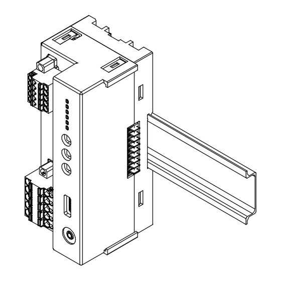
■ HOW TO MOUNT THE MODULE ON DIN RAIL
• Power/Network Module
Position the upper hook at the rear on the DIN rail and push in the lower.
When removing the module, push down the DIN rail adaptor utilizing a
minus screwdriver and pull.
5-2-55, Minamitsumori, Nishinari-ku, Osaka 557-0063 JAPAN
Phone: + 81 ( 6 ) 6659-8201 Fax: + 81 ( 6 ) 6659-8510 E-mail: info@m-system.co.jp
R8-NC3
MODEL
Hook
DIN Rail Adaptor
EM-9726 P. 1 / 7
R8-NC3
Advertisement
Table of Contents

Related Manuals for M-system R8-NC3


Summary of Contents for M-system R8-NC3
- Page 1 • Do not bind these cables together with those in which noises are present. Do not install them in the same duct. EM-9726 P. 1 / 7 5-2-55, Minamitsumori, Nishinari-ku, Osaka 557-0063 JAPAN Phone: + 81 ( 6 ) 6659-8201 Fax: + 81 ( 6 ) 6659-8510 E-mail: info@m-system.co.jp...
- Page 2 ON when abnormal data is received. Green ON with data transmitting Green ON with data receiving EM-9726 P. 2 / 7 5-2-55, Minamitsumori, Nishinari-ku, Osaka 557-0063 JAPAN Phone: + 81 ( 6 ) 6659-8201 Fax: + 81 ( 6 ) 6659-8510 E-mail: info@m-system.co.jp...
- Page 3 OFF = OFF, ON = ON, BL = Blinking ---- = Inconceivable in normal operations (e.g. LED failure) EM-9726 P. 3 / 7 5-2-55, Minamitsumori, Nishinari-ku, Osaka 557-0063 JAPAN Phone: + 81 ( 6 ) 6659-8201 Fax: + 81 ( 6 ) 6659-8510 E-mail: info@m-system.co.jp...
- Page 4 *1. Turn on the terminator DIP switch to activate the internal terminating resistor. EM-9726 P. 4 / 7 5-2-55, Minamitsumori, Nishinari-ku, Osaka 557-0063 JAPAN Phone: + 81 ( 6 ) 6659-8201 Fax: + 81 ( 6 ) 6659-8510 E-mail: info@m-system.co.jp...
- Page 5 RWw n+0 RWr n+0 16 × m (m = cyclic expansion setting) data areas are available for the R8-NC3. In Data Allocation Mode 1, set Cyclic Expansion two (2). When Cyclic Expansion setting is 4, data of module address 32 or larger is invalid.
- Page 6 31_CH2 16 × m (m = cyclic expansion setting) data areas are available for the R8-NC3. Field input data is set at the module’s output data area. The input data area is also secured though not used for an input module.
- Page 7 Input 1 Full interlock Input 2 Partial interlock 1 Input 3 Partial interlock 2 EM-9726 P. 7 / 7 5-2-55, Minamitsumori, Nishinari-ku, Osaka 557-0063 JAPAN Phone: + 81 ( 6 ) 6659-8201 Fax: + 81 ( 6 ) 6659-8510 E-mail: info@m-system.co.jp...
Need help?
Do you have a question about the R8-NC3 and is the answer not in the manual?
Questions and answers