Advertisement
INSTRUCTION MANUAL
NPN TRANSISTOR OUTPUT MODULE
(16 points, full and partial interlock)
BEFORE USE ....
Thank you for choosing M-System. Before use, check the
contents of the package you received as below.
If you have any problems or questions with the product,
please contact M-System's Sales Office or representatives.
■ PACKAGE INCLUDES:
Transistor output module ..............................................(1)
■ MODEL NO.
Confirm that the model number described on the product is
exactly what you ordered.
■ INSTRUCTION MANUAL
This manual describes necessary points of caution when
you use this product, including installation, connection and
basic maintenance procedures.
POINTS OF CAUTION
■ CONFORMITY WITH EU DIRECTIVES
• The equipment must be mounted inside a panel.
• The actual installation environments such as panel con-
figurations, connected devices, connected wires, may affect
the protection level of this unit when it is integrated in
a panel system. The user may have to review the CE re-
quirements in regard to the whole system and employ ad-
ditional protective measures to ensure the CE conformity.
■ GENERAL PRECAUTIONS
• Before you remove or mount the unit, turn off the power
supply and I / O signal for safety.
• Switches on the side of the module can be set for mainte-
nance only while the power supply is off. Do not access
them while the power is supplied.
■ ENVIRONMENT
• Indoor use
• When heavy dust or metal particles are present in the air,
install the unit inside proper housing with sufficient ven-
tilation.
• Do not install the unit where it is subjected to continuous
vibration. Do not apply physical impact to the unit.
• Environmental temperature must be within -10 to +55°C
(14 to 131°F) with relative humidity within 30 to 90% RH
in order to ensure adequate life span and operation.
■ WIRING
• Do not install cables close to noise sources (relay drive
cable, high frequency line, etc.).
• Do not bind these cables together with those in which
noises are present. Do not install them in the same duct.
■ EXCITATION SUPPLY
• Input connector: Rated curent 50mA DC per channel
• Output connector: Rated curent 3A DC (rated current 3A
for internal fuse (slow blow fuse i
t (A
sec) max. 5.04)
2
2
5-2-55, Minamitsumori, Nishinari-ku, Osaka 557-0063 JAPAN
Phone: +81(6)6659-8201 Fax: +81(6)6659-8510 E-mail: info@m-system.co.jp
MODEL
■ AND ....
• The unit is designed to function as soon as power is sup-
plied, however, a warm up for 10 minutes is required for
satisfying complete performance described in the data
sheet.
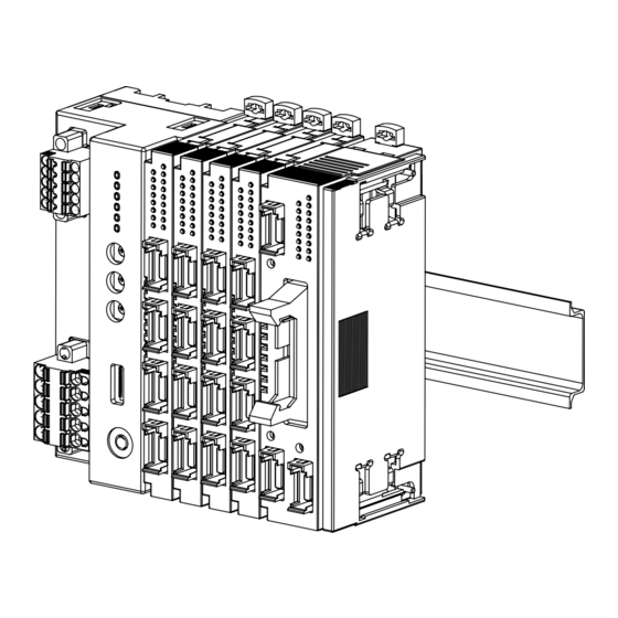
INSTALLATION
■ HOW TO MOUNT THE MODULE ON DIN RAIL
• I/O Module
Confirm that the locking clamps of the I/O module are set.
Insert the module in parallel to the next one while aligning the grooves of
both modules (A & B in the above figure).
Maintain it perpendicularly to the rail.
More I/O modules can be added in the same manner.
R8-DCM16ALH
R8-DCM16ALH
A
B
EM-9746 Rev.2
P. 1 / 5
Advertisement
Table of Contents

Subscribe to Our Youtube Channel
Related Manuals for M-system R8-DCM16ALH


Summary of Contents for M-system R8-DCM16ALH
- Page 1 ■ AND ..BEFORE USE ..• The unit is designed to function as soon as power is sup- plied, however, a warm up for 10 minutes is required for Thank you for choosing M-System. Before use, check the satisfying complete performance described in the data contents of the package you received as below. sheet. If you have any problems or questions with the product, please contact M-System’s Sales Office or representatives.
- Page 2 2) I/O modules cannot hold tightly on the DIN rail by themselves without power/network module. Secure them to the position if necessary by using DIN rail end plates. EM-9746 Rev.2 P. 2 / 5 5-2-55, Minamitsumori, Nishinari-ku, Osaka 557-0063 JAPAN Phone: +81(6)6659-8201 Fax: +81(6)6659-8510 E-mail: info@m-system.co.jp...
-
Page 3: Component Identification
Excitation supply 24 V 17, 18 Excitation supply 0V Discrete input 19, 20 Excitation supply 24V Excitation supply 0 V No connection EM-9746 Rev.2 P. 3 / 5 5-2-55, Minamitsumori, Nishinari-ku, Osaka 557-0063 JAPAN Phone: +81(6)6659-8201 Fax: +81(6)6659-8510 E-mail: info@m-system.co.jp... -
Page 4: Module Address
TERMINATOR SW SW2-6 Without (*) With • Configuration Mode CONFIGURATION MODE SW2-8 DIP switch setting (*) PC Configurator and communicaton Caution: S W2-2 through 2-4 and 2-7 are unused; be sure to turn OFF unused channels. EM-9746 Rev.2 P. 4 / 5 5-2-55, Minamitsumori, Nishinari-ku, Osaka 557-0063 JAPAN Phone: +81(6)6659-8201 Fax: +81(6)6659-8510 E-mail: info@m-system.co.jp... -
Page 5: External Dimensions
Do 12 Do 13 IL1 PARTIAL INTERLOCK 1 Do 14 Do 15 Do 16 Detecting Circuit IL2 PARTIAL INTERLOCK 2 Detecting Circuit EM-9746 Rev.2 P. 5 / 5 5-2-55, Minamitsumori, Nishinari-ku, Osaka 557-0063 JAPAN Phone: +81(6)6659-8201 Fax: +81(6)6659-8510 E-mail: info@m-system.co.jp...
Need help?
Do you have a question about the R8-DCM16ALH and is the answer not in the manual?
Questions and answers