Table of Contents
Advertisement
Quick Links
INTRODUCTION
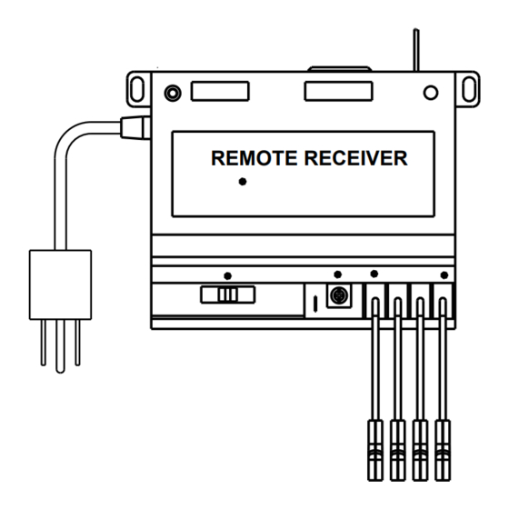
The remote control system can be operated thermostati-
cally or manually from the transmitter. The system oper-
ates on radio frequencies (RF) within a 20 foot range. Can
be used with DSI, IPI or Standing Pilot systems.
This remote control kit has a hand held transmitter that
can be used as a remote on/off or as a thermostat. The
transmitter display shows the current room temperature,
target temperature, timer setting, on/off status, low bat-
tery indicator, current time, burner/valve operation and
fan operation. Electrical ratings for the receiver are: 110
VAC, 60 Hz, 6 W.
If pertinent, see additional fireplace wiring diagrams on
pages 9 to 11.
INSTALLATION PRECAUTIONS
This remote control kit is tested and safe when installed
in accordance with this installation manual.
Installation of this kit MUST be done by a qualified
service technician.
NOTE: A manometer MUST be used to set the
manifold pressure on the gas valve.
It is the responsibility of the installer to read all instruc-
tions before starting installation and to follow these
instructions carefully during installation. Modification of
the remote control system or any of its components will
void the warranty and may cause a fire hazard.
NOTE: The factory installed junction box in the gas
fireplace must be wired with 110 VAC before install-
ing this kit. See Installation Instructions section.
CAUTION: All wiring should be done by a qualified
electrician and shall be in compliance with local codes
and with the National Electric Code ANSI/NFPA No. 70-
current (in the United States), or with the current CSA
C22.1 Canadian Electric Code (in Canada).
WARNING: DO NOT CONNECT 110-120 VAC
WIRING TO THE GAS CONTROL VALVE OF THIS
APPLIANCE.
Hearth & Home Technologies • RCT-MLT-HHT Remote Control Instructions • 100-917 Rev. B • 1/23
RCT-MLT-HHT
Remote Control Kits
- Installation and Operating Instructions -
FCC REQUIREMENTS
WARNING: CHANGES OR MODIFICATIONS TO
THIS UNIT NOT EXPRESSLY APPROVED BY
THE PARTY RESPONSIBLE FOR COMPLIANCE
COULD VOID THE USER'S AUTHORITY TO OPER-
ATE THE EQUIPMENT.
NOTE: This equipment has been tested and found
to comply with the limits for a Class B digital device,
pursuant to Part 15 of the FCC Rules. These limits are
designed to provide reasonable protection against harm-
ful interference in a residential installation. This equip-
ment generates, uses, and can radiate radio frequency
energy and, if not installed and used in accordance with
the instructions, may cause harmful interference to radio
communications. However, there is no guarantee that
interference will not occur in a particular installation. If
this equipment does cause harmful interference to radio
or television reception, which can be determined by turn-
ing the equipment off and on, the user is encouraged
to try to correct the interference by one or more of the
following measures:
- Reorient or relocate the receiving antenna.
- Increase the separation between the equipment and
receiver.
- Connect the equipment into an outlet on a circuit dif-
ferent from that to which the receiver is connected.
- Consult the dealer or an experienced radio TV techni-
cian for help.
Canadian Equipment Requirements
This digital apparatus does not exceed the (Class A/
Class B)* limits for radio noise emissions from digital
apparatus set out in the Radio Interference Regulations
of the Canadian Department of Communications.
Le present appareil numerique n'emet pas de bruits
radioelectriques depassant les limites applicables aux
appareils numeriques (de la class A/de la class B)* pres-
crites dans le Reglement sur le brouillage radioelectrique
edicte par le ministere des Communications du Canada.
This device complies with RSS-210 of Industry and Sci-
ence Canada. Operation is subject to the following two
conditions: (1) this device may not cause interference,
and (2) this device must accept any interference, includ-
ing interference that may cause undesired operation of
the device.
1
Advertisement
Table of Contents

Related Manuals for Hearth & Home RCT-MLT-HHT


Summary of Contents for Hearth & Home RCT-MLT-HHT
- Page 1 (1) this device may not cause interference, and (2) this device must accept any interference, includ- ing interference that may cause undesired operation of the device. Hearth & Home Technologies • RCT-MLT-HHT Remote Control Instructions • 100-917 Rev. B • 1/23...
-
Page 2: Installation Instructions
4. Re-attach the cover plate to the outside of the fireplace. WARNING: LEAVE ELECTRICAL POWER OFF AT THIS TIME. DO NOT RESTORE POWER UN- TIL THE REMOTE CONTROL SYSTEM IS COM- PLETELY INSTALLED. Hearth & Home Technologies • RCT-MLT-HHT Remote Control Instructions • 100-917 Rev. B • 1/23... - Page 3 (Receptacle on back) Line cord REMOTE RECEIVER from fan REMOTE RECEIVER VALVE Figure 3. Adding Fan/Blower ON/OFF SWITCH REMOTE SWITCH PIGTAIL BROWN WALL SWITCH Figure 2. Hearth & Home Technologies • RCT-MLT-HHT Remote Control Instructions • 100-917 Rev. B • 1/23...
- Page 4 Adjust until the reading on Figure 5. the manometer is 3.5 inches w.c. for natural gas, or 10.0 inches w.c. for LP. Hearth & Home Technologies • RCT-MLT-HHT Remote Control Instructions • 100-917 Rev. B • 1/23...
- Page 5 Placing the switch in the OFF position also functions as a safety “lock out” by turning the system off and rendering the remote receiver inoperative. Hearth & Home Technologies • RCT-MLT-HHT Remote Control Instructions • 100-917 Rev. B • 1/23...
- Page 6 • THERMO indicates the system will automatically cycle ON/OFF, depending on programmed set tempera- ture. • OFF indicates the entire system is turned off. Hearth & Home Technologies • RCT-MLT-HHT Remote Control Instructions • 100-917 Rev. B • 1/23...
- Page 7 2. Press the UP or DOWN button to select the desired room temperature. The highest SET temperature is 99º F (32º C). The lowest SET temperature is 45º F (6º C). Hearth & Home Technologies • RCT-MLT-HHT Remote Control Instructions • 100-917 Rev. B • 1/23...
-
Page 8: Low Battery Indicator
5. Press the MODE button on the transmitter to change ing that the transmitter is within the normal operating the system to THERMO. range of 20 feet. Hearth & Home Technologies • RCT-MLT-HHT Remote Control Instructions • 100-917 Rev. B • 1/23... -
Page 9: General Information
You may have for labor charges and/or damage incurred in installation, other rights that vary by state, province or nation. Hearth & Home Technologies • RCT-MLT-HHT Remote Control Instructions • 100-917 Rev. B • 1/23... - Page 10 WIRE ASSEMBLY VALVE Figure 9. Intermittent Pilot Ignition (IPI) Wiring Diagram PIEZO PILOT THERMOSTAT WIRE ASSEMBLY THERMOCOUPLE VALVE Figure 10. Standing Pilot Ignition Wiring Diagram Hearth & Home Technologies • RCT-MLT-HHT Remote Control Instructions • 100-917 Rev. B • 1/23...
- Page 11 PLUG IN CHASSIS JUMPER WIRE (TO BROWN) (WHEN APPLICABLE) VALVE BATTERY PACK FLAME SOLENOID ADAPTER WIRES Figure 11. Remote Control Intermittent Pilot Ignition (IPI) Wiring Diagram Hearth & Home Technologies • RCT-MLT-HHT Remote Control Instructions • 100-917 Rev. B • 1/23...
- Page 12 For the location of your nearest Hearth & Home Technologies dealer, please visit www.hearthnhome.com. Hearth & Home Technologies 7571 215th Street West, Lakeville, MN 55044 www.hearthnhome.com Hearth & Home Technologies • RCT-MLT-HHT Remote Control Instructions • 100-917 Rev. B • 1/23...
Need help?
Do you have a question about the RCT-MLT-HHT and is the answer not in the manual?
Questions and answers