Daikin FXFN71A2VEB Installation And Operation Manual
Indoor unit
Hide thumbs
Also See for FXFN71A2VEB:
- Installer and user reference manual (88 pages) ,
- Installation and operation manual (28 pages)

Related Manuals for Daikin FXFN71A2VEB


Summary of Contents for Daikin FXFN71A2VEB
- Page 1 Installation and operation manual CO₂ Conveni-Pack: indoor unit FXFN50A2VEB Installation and operation manual FXFN71A2VEB English CO₂ Conveni-Pack: indoor unit FXFN112A2VEB...
- Page 2 2P613087-2G...
-
Page 3: Table Of Contents
14 Electrical installation 14.1 Specifications of standard wiring components ......19 ▪ The full set of latest technical data is available on the Daikin 14.2 To connect the electrical wiring to the indoor unit ..... 20 Business Portal (authentication required). -
Page 4: Specific Installer Safety Instructions
WARNING Make sure installation, servicing, maintenance, repair and ▪ Expanding of pipes is NOT allowed. applied materials follow the instructions from Daikin and, in CAUTION addition, comply with applicable legislation and are performed by qualified persons only. In Europe and areas... -
Page 5: For The User
3 User safety instructions WARNING WARNING ▪ If the power supply has a missing or wrong N-phase, Use an all-pole disconnection type breaker with at least equipment might break down. 3 mm between the contact point gaps that provide full disconnection under overvoltage category III. -
Page 6: Instructions For Safe Operation
3 User safety instructions Instructions for safe operation CAUTION To avoid oxygen deficiency, ventilate WARNING the room sufficiently if equipment with Do NOT modify, disassemble, remove, burner is used together with the reinstall or repair the unit yourself as system. incorrect dismantling or installation may cause an electrical shock or fire. -
Page 7: About The System
4 About the system WARNING poisoning. Ventilate the room and contact the dealer where you NEVER replace a fuse with a fuse of a purchased the unit (see "7.3.1 About wrong ampere ratings or other wires detection" [ 4 11]). refrigerant leak when a fuse blows out. -
Page 8: User Interface
5 User interface NOTICE Do NOT wipe the controller operation panel with benzine, thinner, chemical dust cloth, etc. The panel may get discoloured or the coating peeled off. If it is heavily dirty, soak a cloth in water-diluted neutral detergent, squeeze it well and wipe the panel clean. -
Page 9: Special Heating Operation Modes
7 Maintenance and service Icon Operation mode INFORMATION Fan only. In this mode, air circulates without heating Depending on system layout and organisation, Auto airflow or cooling. direction may not be available. Dry. In this mode, the air humidity will be lowered with INFORMATION a minimal temperature decrease. -
Page 10: Cleaning The Air Filter, Suction Grille, Air Outlet And Outside Panels
7 Maintenance and service ▪ Depending on the settings, the user interface can display the CAUTION: Pay attention to the fan! "Time to clean filter" notification. Clean the air filter when the It is dangerous to inspect the unit while the fan is running. notification is displayed. -
Page 11: To Clean The Suction Grille
7 Maintenance and service 6 Turn ON the power. 7.2.3 To clean the air outlet and outside panels 7 To remove warning screens, see the reference guide of the WARNING user interface. indoor unit wet. Possible 7.2.2 To clean the suction grille consequence: Electrical shock or fire. -
Page 12: Troubleshooting
8 Troubleshooting INFORMATION Malfunction Measure The operation switch does NOT function Turn OFF the power During detection of the refrigerant leakage, the contact properly. supply. between terminals T1 and T2 disconnects. During normal operation, the contact between terminals T1 and T2 is Notify your installer and If the user interface displays or an... -
Page 13: For The Installer
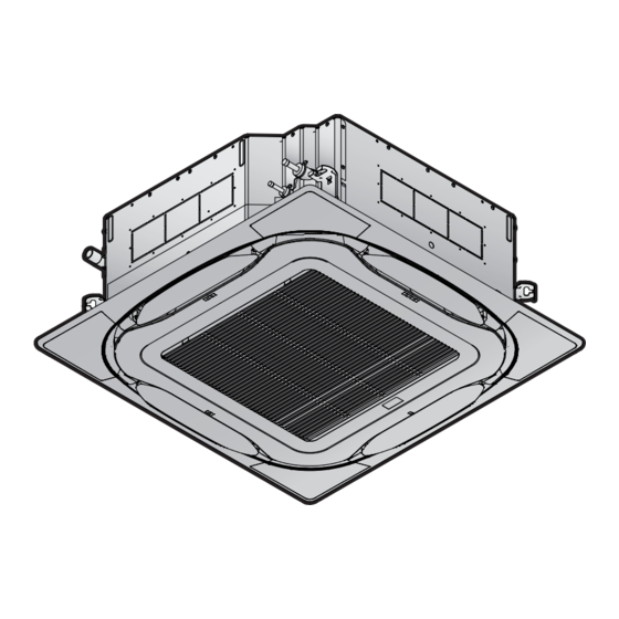
11 About the box For the installer 12.1 Preparing the installation site About the box Avoid installation in an environment with a lot of organic solvents such as ink and siloxane. 11.1 Indoor unit 12.1.1 Installation site requirements of the 11.1.1 To remove the accessories from the indoor unit... -
Page 14: Additional Installation Site Requirements For Co₂ Refrigerant
12 Unit installation ≥311 mm: In case of installation with standard decoration Appropriate measures panel ≥353 mm: In case of installation with design decoration INFORMATION panel ≥391 mm: In case of installation with auto cleaning Appropriate measures are field supply. Choose and install decoration panel all required appropriate measures in accordance with ≥361 mm: In case of installation with standard panel +... -
Page 15: Mounting The Indoor Unit
12 Unit installation Example: Total refrigerant charge in the system is 45 kg and room INFORMATION volume is 300 m . 45/300=0.15, which is >QLMV (0.074) and Even if there is no refrigerating system on the lowest floor, <QLAV (0.18), therefore install at least 1 appropriate measure in the where the largest system charge (kg) in the building room. -
Page 16: Guidelines When Installing The Drain Piping
12 Unit installation ▪ Paper pattern for installation (upper part of the packing). Use the paper pattern to determine the correct horizontal positioning. It contains the necessary dimensions and centers. You can attach the paper pattern to the unit. Centre of the unit Centre of the ceiling opening Paper pattern for installation (upper part of the packing) In case of installation with standard decoration panel... - Page 17 12 Unit installation Allowed Not allowed ▪ Condensation. Take measures against condensation. Insulate the complete drain piping in the building. ▪ Rising piping. If necessary to make the slope possible, you can install rising piping. ▪ Drain hose inclination: 0~75 mm to avoid stress on the piping and to avoid air bubbles.
-
Page 18: Piping Installation
13 Piping installation Refrigerant piping diameter Liquid piping Gas piping Ø9.5 mm Ø12.7 mm Refrigerant piping material ▪ Piping material: K65 copper-iron alloy (CuFe2P), maximum operating pressure = 120 bar ▪ Piping temper grade and thickness: Outer diameter Temper grade Thickness (t) (Ø) Ø... -
Page 19: Electrical Installation
14 Electrical installation Brazed connection WARNING Refrigerant pipe connection (attached to the unit) ▪ Use K65 piping for high-pressure applications with a Unit Sealing pads: Medium 1 (gas pipe), medium 2 (liquid working pressure of 120 bar or 90 bar, depending on its pipe) (accessories) location in the system. -
Page 20: To Connect The Electrical Wiring To The Indoor Unit
14 Electrical installation Opening for cables 14.2 To connect the electrical wiring to Connection of power supply the indoor unit Tie wrap Connection of user interface and transmission cable NOTICE Complete system example ▪ Example: 1 user interface controls 1 indoor unit. ▪... -
Page 21: Commissioning
Next Do NOT interrupt the test run. commissioning instructions in this chapter, a general commissioning checklist is also available on the Daikin Business Portal (authentication required). Configuration The general commissioning checklist is complementary to the instructions in this chapter and can be used as a guideline and reporting template during the commissioning 16.1... - Page 22 16 Configuration INFORMATION If you want… Then SW/C1 —/C2 ▪ The connection of optional accessories to the indoor unit might cause changes to some field settings. For During thermostat 12 (22) more information, see the installation manual of the OFF at cooling Setup volume optional accessory.
-
Page 23: Technical Data
▪ A subset of the latest technical data is available on the regional Daikin website (publicly accessible). FU*, F*U, (for characteristics, Fuse refer to PCB inside your unit) ▪ The full set of latest technical data is available on the Daikin Business Portal (authentication required). Connector (frame ground) Harness H*P, LED*, V*L... - Page 24 17 Technical data Symbol Meaning Symbol Meaning Intelligent eye sensor Ferrite core IPM* Intelligent power module ZF, Z*F Noise filter K*R, KCR, KFR, KHuR, K*M Magnetic relay Live Coil Reactor Stepper motor Compressor motor Fan motor Drain pump motor Swing motor MR*, MRCW*, MRM*, MRN* Magnetic relay Neutral...
- Page 28 3P672850-1B 2022.01 Verantwortung für Energie und Umwelt...
Need help?
Do you have a question about the FXFN71A2VEB and is the answer not in the manual?
Questions and answers