Daikin Rebel Applied DPSA Installation And Start-Up Manual
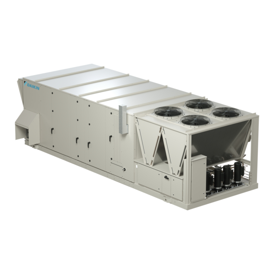
Packaged rooftop
Hide thumbs
Also See for Rebel Applied DPSA:
- Installation and start-up manual (118 pages) ,
- Installation and start-up manual (180 pages) ,
- Installation operation & maintenance (188 pages)

Related Manuals for Daikin Rebel Applied DPSA


Summary of Contents for Daikin Rebel Applied DPSA
- Page 1 Installation and Start-up Manual IM 1287-4 Group: Applied Air Handling Part Number: IM 1287 Date: April 2022 Rebel Applied Packaged Rooftop ™ Heating and Cooling Models DPSA 30 to 52 Tons R-410A Refrigerant...
-
Page 2: Table Of Contents
Table of Contents Table of Contents Introduction . . . . . . . . . . . . . . . . . . . . . . . . . . . . . . . . . . . . . . . 4 Installing Discharge Air Temperature Sensor . - Page 3 Restart........99 Daikin Electric Heater Modules..... 100 Electric Heater General Information .
-
Page 4: Introduction
Unit Operations and DPSA OM 1288 Maintenance WARNING Non-Daikin See vendor manuals Warning indicates potentially hazardous situations for PVC (Polyvinyl Chloride) and CPVC (Chlorinated Polyvinyl Chloride) piping in chilled water Nameplate Information systems. In the event the pipe is exposed to POE (Polyester) oil used in the... -
Page 5: Unit Description
Introduction Figure 1: Nomenclature D PS A 050 A 4 B S Daikin Rebel Cooling Configuration 0 = No cooling, heat only C = Chilled water coil Packaged DX Cooling System S = Standard efficiency air-cooled DX PS = Packaged DX Cooling... - Page 6 Introduction Figure 3: Typical Component Locations—DPS-A Units Top View Condensate Connection 1.5” NPT Bottom Discharge Air Opening Bottom Return Air Opening Side View Filter Outside/Return Air Dampers Condenser Fan Supply Air Fan (Economizer Dampers) Outdoor Air Hood Exhaust Hood Low Voltage Control Panel Evaporator Heat Section (Natural Gas,...
- Page 7 Introduction Figure 4: ECM Fan Array Identification www.DaikinApplied.com IM 1287-4 • REBEL APPLIED ROOFTOP...
-
Page 8: Refrigeration Piping
Introduction Refrigeration Piping This section presents the unit refrigeration piping diagrams for the various available configurations. Figure 5: Schematic, Standard Circuit Figure 6: Schematic, Hot Gas Bypass Circuit IM 1287-4 • REBEL APPLIED ROOFTOP www.DaikinApplied.com... - Page 9 Introduction Figure 7: Schematic, MHGRH Circuit Figure 8: Schematic, LSCRH Circuit 1 www.DaikinApplied.com IM 1287-4 • REBEL APPLIED ROOFTOP...
- Page 10 Introduction Figure 9: Schematic, LSCRH Circuit 2 Figure 10: Low Ambient Circuit Schematic Low Ambient Configurations Speedtrol (Variable speed fans) down to 25F Speedtrol (Variable speed fans) + Splitter solenoid down to -10F IM 1287-4 • REBEL APPLIED ROOFTOP www.DaikinApplied.com...
- Page 11 Introduction Figure 11: Variable Speed Cooling Circuit Diagram www.DaikinApplied.com IM 1287-4 • REBEL APPLIED ROOFTOP...
-
Page 12: Condenser And Compressor Piping
Introduction Condenser and Compressor Piping Figure 12: Condenser Piping, Compressors, 1 to 2 Compressors per Circuit are Provided* Ckt 2 Splitter Solenoid (optional) Comp 4 Suction Shut-off Valve (optional) Ckt 1 Comp 2 Comp 3 Comp 1 To DX Coil Optional Refrigerant Hot gas Bypass Temperature and Pressure... - Page 13 Introduction Figure 13: Condenser and Compressor Piping (Inverter Compressors) Figure 14: Inverter Compressor Piping Detail www.DaikinApplied.com IM 1287-4 • REBEL APPLIED ROOFTOP...
-
Page 14: Vfd Inverter Box
Introduction VFD Inverter Box Figure 15: VFD Inverter Box Refrigerant Connections, Front Figure 16: VFD Inverter Box Refrigerant Connections, Back IM 1287-4 • REBEL APPLIED ROOFTOP www.DaikinApplied.com... - Page 15 Introduction Figure 17: VFD Inverter Box Components www.DaikinApplied.com IM 1287-4 • REBEL APPLIED ROOFTOP...
-
Page 16: Controlled Component Locations
Introduction Controlled Component Locations Figure 18 shows basic control and component locations within a typical unit Figure 18: Control and Component Locations Outdoor Air Pre Heater Energy Wheel Energy Wheel Control Box Leaving Wheel Temp. Sensor Outside Air Damper Exhaust Fans Energy Recovery VFD... -
Page 17: Control Panel
Introduction Control Panel The unit control panels and their locations are shown in the following figures. These figures show a typical unit. Specific unit configurations may differ. Figure 19: Control Panel Locations Energy Wheel /Electric Pre heater Control Panel (if applicable) Low Voltage Control Panel... - Page 18 Introduction Figure 21: Typical Low Voltage Control Panel Figure 22: Typical Return Control Panel (with Prop Exhaust Fan VFD) IM 1287-4 • REBEL APPLIED ROOFTOP www.DaikinApplied.com...
- Page 19 Introduction Figure 23: Typical Return Control Panel (without Prop Exhaust Fan VFD) Figure 24: Typical Return Control Panel (with Energy Recovery Wheel) www.DaikinApplied.com IM 1287-4 • REBEL APPLIED ROOFTOP...
-
Page 20: Installation
(with Receiving Inspection a crane) after removing roof panels. Also, Daikin recommends providing a roof walkway to the rooftop unit, as well as along When the equipment is received, all items should be carefully... -
Page 21: Ventilation Clearance
Installation Figure 26: Service Clearances (Scenario B) Condenser Section Heat Section Supply Fan Section Filter section Return 48” Section 96” 48” 48” 72” To roof access location Recommended roof walkway Ventilation Clearance Figure 27 denotes minimum ventilation clearance Do not locate outside air intakes near exhaust vents or other recommendations. -
Page 22: Overhead Clearance
Installation Overhead Clearance 1. If clearances from Scenario B (Figure 26) are applied to 4. The following restrictions must be observed for overhead the installation, then unit must not have any overhead obstructions above the air handler section where ground obstructions over any part of the unit. -
Page 23: Roof Curb Assembly And Installation
Installation Roof Curb Assembly and Installation Curb Assembly instructions WARNING Mold can cause serious illness and property damage. Some materials 1. Set curbing parts in accordance with assembly such as gypsum wall board can promote mold growth when damp. Such instructions provided with unit. - Page 24 Installation Figure 29: B – Standard Plenum Curb Assembly Figure 30: Full Perimeter Plenum Curb Assembly IM 1287-4 • REBEL APPLIED ROOFTOP www.DaikinApplied.com...
- Page 25 Installation Figure 31: B – Full Perimeter Roof Curb Assembly Figure 32: Detail Views Detail A Detail B 1. Unit Base 2. Curb Gasketing 3. 2x4 Nailer Strip 4. Galvanized Curb 5. Cant Strip (not furnished) 6. Roofing Material (not furnished) 7.
-
Page 26: Full Condenser Floor Sealing
Installation Full Condenser Floor Sealing 3. As conduit is installed for wires, caulk or some other CAUTION watertight seal must be added at point where the conduit All penetrations made through full condenser floor models must be sealed meets the condenser floor in order to prevent leaks to prevent leaks. - Page 27 Installation Table 2: Rebel Applied Roof Curb Assembly Dimensions, Table 3: Rebel Applied Roof Curb Assembly Dimensions, Return Configurations Supply Configurations Unit Supply Unit Return size Configuration in . in . in . in . (mm) in . (mm) in . (mm) in . (mm) in . (mm) Size Configuration in .
-
Page 28: Post And Rail Mounting
Installation Post and Rail Mounting Rigging and Handling WARNING Cabinet Weather Protection The unit must be level side to side and over the entire length. Equipment CAUTION damage can result if the unit is not level. Transportation, rigging, or maintenance can damage the unit’s weather seal. Periodically inspect the unit for leakage. - Page 29 Installation Lifting Points properly installed and fully closed to prevent the entry of animals and debris through the supply and return air Lifting points are predetermined from factory. When lifting, openings. make sure all factory installed lifting lugs are used. Figure 7.
-
Page 30: Shipping Splits
Installation Shipping Splits Reassembly of Shipping Splits The cabinet modules must be reassembled on the roof curb in the proper order. The return section should be set in place DPSA units are typically shipped complete, however, an first, followed by the center section (if applicable), and the optional configuration is available that allows for the unit to be condenser section last (Figure... - Page 31 Installation NOTE: Do not remove the Internal stiffeners at this time. The design of the lifting lugs is such to help align the 2 They will help keep the cabinet square during the lift sections on the curb. It is critical that the unit base is co-planar of the module to the roof curb (Figure down the air tunnel.
- Page 32 Installation 7. Place and fasten deck panel to base (Figure 48). All 10. Add rain covers (Figure 52) by liberally applying caulk fasteners in the deck panel need to be fastened to a (Figure 51) to prevent leaks from rain or moisture. Tip torque of 35 in·lbs and approximately flush with the deck hemmed lip in under previous rain cover (Figure...
- Page 33 Installation 12. Install raceway junction box and connect the wiring. 14. Install the high-to-low voltage divider (Figure 57). DANGER Figure 57: High-to-Low Voltage Divider LOCKOUT/TAGOUT all power sources prior to wiring or servicing the unit. Hazardous voltage can cause serious injury or death. Disconnect electric power before servicing equipment.
- Page 34 Installation 17. Connect the wires per the wiring schematic. In the low 19. Attach the high voltage cover (Figure 62). voltage raceway, connect the plugs that mate. The wires should be routed up to the platform and wire-tied such Figure 62: High Voltage Cover that the plugs sit on the platform.
- Page 35 Installation Given refrigerant piping is separated by shipping splits, the Figure 66: Tape Location procedure must be followed through per the unit’s refrigerant system requirements. Figure 64 illustrates couplers and extensions to be added upon installation. Tube sizes and couplers must match manufactured tube sizes. Figure 64: Couplers and Extensions CAUTION Protect wire harness from brazing heat, which can cause severe equipment...
-
Page 36: Reconnecting Power And Control Wire
If you need WARNING assistance on these procedures, please contact Daikin Drain pans must be cleaned periodically. Uncleaned drain pans can cause Applied Technical Response Center. -
Page 37: Hot Water Or Hot Water Integral Face And Bypass
Some products have higher freezing points in their natural state than when mixed with water. The freezing of coils is not the responsibility of Daikin. Hot water coils are not normally recommended for use with entering air temperatures below 35°F (1.6°C). - Page 38 Installation Figure 71: Hot Water Heat Section (Shown with Factory Valve and Piping, no Bypass) Supply Return Return NOTE: Horizontal Supply and Return will be through the fixed panel in line with the pipe connections. Figure 72: IFB Hot Water IM 1287-4 •...
-
Page 39: Steam Coil Or Steam Integral Face And Bypass Coil
Installation Figure 73: Hot Water Bypass Valve Package Bypass Valve Table 7: Steam Connection Size Steam Coil or Steam Integral Face and Bypass Coil Steam Connections Steam coils are provided without valves as a standard unit, Cabinet All Rows 2” requiring field installation of valves and piping. - Page 40 Installation Figure 75: Steam Heat Section (Valve and Factory Piping) Supply Return IM 1287-4 • REBEL APPLIED ROOFTOP www.DaikinApplied.com...
- Page 41 Installation Steam Piping Recommendations Steam Coil Freeze Conditions 1. Be certain that adequate piping flexibility is provided. If the air entering the steam coil is below 35°F (2°C), note the Stresses resulting from expansion of closely coupled following recommendations: piping and coil arrangement can cause serious damage. 1.
-
Page 42: Damper Assemblies
Installation Damper Assemblies Intake Hood Damper (0% to 100% The optional damper assemblies described in this section normally are ordered with factory-installed actuators and outside air) linkages. The following sections describe operation and linkage adjustment of the factory-installed air damper options. Units requiring 100% outside air are provided with a rain hood and dampers that can be controlled by a single actuator. -
Page 43: Exhaust Hood Assembly
Installation Figure 77: Intake Hood Damper Adjustment 2. Fold top of hood up. 0% Outside Air 3. Fold left side and right side out and put screws provided with unit into corresponding holes to lock in position of left side and top of the hood as shown in Figure 79 (reinstall 2 shipping screws and use 4 additional screws provided with unit). -
Page 44: Hepa Holding Frame, Filter, And Prefilter Installation
Installation HEPA Holding Frame, Filter, and Figure 81: Leg Extensions and Latches With Prefilters Prefilter Installation WARNING Sharp edges on sheet metal and fasteners can cause personal injury. Please wear appropriate personal protective equipment (PPE) such as gloves, protective clothing, footwear, eye protection, etc. This equipment must be installed, operated, and serviced only by an experienced installation company and fully trained personnel. - Page 45 Installation Figure 84: Frame with Leg Extensions Installed The filter should now be resting inside of the holding frame. When installing the filters into a frame bank of multiple frames, install the lower filters first so that the upper filters can rest on the lower filters (Figure 86).
-
Page 46: Aaf Hepa Filters With Prefilters
Installation AAF HEPA Filters with Prefilters STEP 4: Once all four corner latches have been tightened within 1/4” of the leg extension coupling, complete the Follow previous steps 1-2, then continue straight to step 5. installation by tightening each corner until the latch and leg extension coupling meet. - Page 47 Installation Figure 93: Tighten Cap Screw to 1/4” of the Coupling STEP 8: To complete the installation, add the appropriate prefilter latches to the prefilter holding frame (Figure 96). Once latches are installed, place the prefilter in the frame, secure with the latches and the installation is complete (Figure 97).
-
Page 48: Installing Ductwork
2. Differentiate between the duct pressure (HI) and reference pressure (LO) taps by using different color On bottom-supply/bottom-return units, if a Daikin roof curb tubing or by tagging the tubes. Daikin recommends 3/16ʺ is not used, installing contractor should make an airtight I.D. plastic tubing. -
Page 49: Fan Block-Off Plates
Installation Fan Block-off Plates Downstream Fan Block-off Plate Optional fan block-off plates may be ordered to HELP maintain reduced capacity functionality in the case of a supply or return fan failure. A until replacement can be procured and installed. Downstream fan block-off plates are an option that requires Fan block-off plates come in two styles, upstream and removing the failed fan. -
Page 50: Top Discharge
Installation Top Discharge Side Discharge On units that are in the top discharge configuration, it is the On units that are in the side discharge configuration, The same installer’s responsibility to ensure there can be no leakage at rules as top discharge for unit leakage apply. It is the installer’s or around the duct collar, or the applied ductwork. -
Page 51: Installing Building Static Pressure Sensor Taps
2. Differentiate between the building pressure (HI) and Sensor outdoor pressure (LO) taps by using different color tubing or by tagging the tubes. Daikin recommends 3/16ʺ I.D. The discharge air temperature sensor should be installed in plastic tubing. the supply air duct. downstream of the rooftop unit. Locate the sensor at a location that approximates the average duct 3. -
Page 52: Unit Wiring
More than one disconnect may be Schematics to determine if the electric heater will require its required to de-energize the unit. own set of service conductors. Refer to “Daikin Electric Heater Modules” on page 100 for service conductor entrance details DANGER pertaining to the electric heater. - Page 53 Unit Wiring Table 9: Non-Fused Disconnect Lug Port Details Copper wire is required for all field installed conductors. Supply voltage must not vary by more than 10% of the unit Non Fused Type 1 Ports Type 2 Ports voltage specified on the nameplate. Phase voltage imbalance Disconnect Min Awg Max Awg must not exceed +/- 2%.
- Page 54 Unit Wiring Figure 108: Typical Field Power Entrance – Panel Entrance Plate Figure 109: Field Wired GFCI Power IM 1287-4 • REBEL APPLIED ROOFTOP www.DaikinApplied.com...
-
Page 55: Field Control Wiring
Unit Wiring Field Control Wiring Figure 110: Graphical Representation of TB2 DANGER LOCKOUT/TAGOUT all power sources prior to wiring or servicing the unit. Electrical shock hazard that may cause severe injury or death. Connect only low voltage NEC Class II circuits to the Error! Reference source not found. Error! Reference source not found.. - Page 56 Unit Wiring Rebel Applied units operate with 115V and 24V control circuit power. All field control wiring connections are made at the class II terminal block TBLV2 which is located in the Low Voltage Control Panel, shown in Figure 112 NOTE: The installation of all field wiring, must comply with all applicable local codes and ordinances.
-
Page 57: Field Output Signals
Unit Wiring Field Output Signals There are several output signals on the MicroTech 4 Controller Figure 113: Field Output Schematic that may be available for field connections. For example, the Alarm Output and the Auxiliary Output, shown in Figure 113, can be used to send signals to external systems. -
Page 58: Unit Operation
Unit Operation Unit Operation Preparing Unit for Operation Power-up Fan Operation There is a 115 VAC control circuit transformer and several Within 120 seconds after the fans start, the controller expects 24VAC circuit transformers within the unit to control the various to get feedback from the fans (via modbus) that they are loads and sensors within the unit. -
Page 59: Compressor Operation
Unit Operation Compressor Operation 4 Compressor - 4 Fixed device also protects against phase reversal when improper phase sequence is applied to equipment, and low voltage In this configuration there are four fixed speed compressors (brownout) when all three line voltages drop to 90% or less of split into two equally sized cooling circuits. -
Page 60: Mhgrh Control & Arrangement
Unit Operation Modulating Hot Gas Reheat (MHGRH) arrangement, with both the condenser and reheat coils of the micro channel type, three-way modulating reheat valve Modulating hot gas reheat (MHGRH) systems redirect a and dual check valves. MHGRH components will always be portion of the hot refrigerant coming from the compressor(s) on installed in circuit #1. -
Page 61: Mlscrh+Mhgrh Control & Arrangement
Unit Operation valves shall be 1% per sec (or 0.1V per sec). valves to their minimum position (0%) for an additional 60 seconds. The reheat valves will also be synchronized if • The reheat valve stepper motor will require occasional there are unexpected system responses in relation to the re-synchronization to assure the motor and driver remain valves position. -
Page 62: Steam Supply Line Connection
Unit Operation Steam Supply Line Connection Follow the below general installation rules in order to avoid any condensation accumulation which can cause Table 13 shows the pipe connection sizes. severe water accumulation in the duct or a humidifier malfunction . Table 13: Humidifier Connections Sizes IMPORTANT Number... -
Page 63: Vav Box Output
Unit Operation Troubleshooting added condensation losses. Whenever possible, use insulated copper piping. Flexible steam hose should be used for short runs (up to 15 feet or 5m) or for Problem Causes Corrective Actions interconnecting between the rigid pipe runs. For longer •... -
Page 64: Entering Fan Temperature Sensor
Unit Operation Entering Fan Temperature Sensor Propeller Exhaust Fan Option The entering fan temperature (EFT) sensor and an associated Economizer units may include propeller exhaust or centrifugal “Lo Airflow Problem” alarm are provided on VAV units with return fan options. This section covers maintenance and MicroTech 4 control and gas or electric heat. -
Page 65: Fan Prestarting Checks
Unit Operation Fan Prestarting Checks Ultraviolet Lights Option Check all fasteners and set screws for tightness. This is When this option is employed, ultraviolet C light bathes especially important for bearing set screws. the moist surfaces on the coil and drain pan, killing most microorganisms that can grow there. -
Page 66: Convenience Receptacle/Section Lights
Warranty Registration Form” on page 115 and return it to 10. Verify all fasteners on the fan assemblies are still tight. Daikin. 11. Verify that the evaporator condensate drain trap is A representative of the owner or the operator of the equipment installed and that the drain pan is level. -
Page 67: Initial Manual Mode Start-Up
Unit Operation Initial Manual Mode Start-Up OA Damper Start-up Initial Start-up should be performed in manual control mode 1. Check whether the outdoor air is suitable for free cooling Main Menu\Manual before proceeding to the cooling/heating start up. by displaying the keypad menu Control\OA Damper Position=30%. -
Page 68: Cooling/Heating Start Up
Unit Operation Cooling/Heating Start up Fixed Speed Compressor Startup CAUTION Supply Fan Start-up Low ambient temperature can cause compressor damage. Do not attempt 1. Verify all duct and unit mounted isolation dampers are to start up and check the refrigeration system when the outdoor air open. - Page 69 Unit Operation Scroll Compressor Rotational Direction Scroll compressors only compress in one rotational direction. 7. The compressor should operate continuously while there Three-phase compressors can rotate in either direction is a call for cooling. If the compressor cycles on its low depending upon phasing of the power to L1, L2, and L3.
-
Page 70: Expansion Valve Superheat Adjustment (Thermal Expansion Valve)
Unit Operation Expansion Valve Superheat Adjustment Air Balancing (Thermal Expansion Valve) DANGER It is very important that the expansion valve superheat setting Moving Machinery hazard. Moving components such as, fans, dampers, be adjusted to be between 10°F (–12°C) and 14°F (–10°C). energy recovery devices can cause serious injury or death. - Page 71 Unit Operation Main 5. Set the compressor lead/lag function as desired using 9. Set the control timers as required in keypad menu Main Menu\Advanced Menus\Cooling Menu\Commission Unit\Timer Settings. keypad menu Setup\Lead Circuit Main Menu\Advanced Menus\ Setup/ a. Set the date and time in keypad menu Cooling Setup\Load Method = Lead Load Cross Load Service\Time/Date\.
-
Page 72: Maintaining Control Parameter Records
The first line on each page includes the page title and the line number to which the cursor is currently “pointing”. The line Daikin recommends that the MicroTech 4 controller’s setpoints numbers are X/Y to indicate line number X of a total of Y lines and parameters be recorded and saved for future reference. -
Page 73: Navigation Mode
“main menu” is reached. Figure 126: Password Main Page When the Menu (Home) Button is pressed the display reverts to the “main page.” Daikin AHU When the Alarm Button is depressed, the Alarm Lists menu is displayed. Enter Password... -
Page 74: Smoke And Fire Protection
Sequences - the ventilation control feature allows for one of Daikin optionally offers factory installed outdoor air, return the following sequences to be performed. air, and exhaust air dampers as well as smoke detectors in... - Page 75 Unit Operation Emergency Shutdown coils. The sensing element is located on the downstream side of the heating coil in the heating section of the unit. If The terminals 205 & 206 on TB2 can be used for any field the freezestat detects a freezing condition and closes, the supplied component that requires a unit emergency shutdown.
-
Page 76: Microtech ® 4 Remote User Interface
Features In addition to the unit-mounted user interface provided with MicroTech 4 controls, Daikin applied rooftop systems can • Can be wired up to 700 meters from units for flexibility in be equipped with a remote user interface that handles up to placing each remote user interface within your building. -
Page 77: Microtech 4 Field Installed Sensors
Figure 133: Network Space Sensor The MicroTech 4 unit controller can be connected to a variety of field installed sensors. • Space Sensor with tenant override – Daikin PN: 113117701 • DDC Space Sensor with Setpoint Adjust and Tenant Override – Daikin PN: 910143408 •... -
Page 78: Keypad And Display Menu Structure
Unit Operation Keypad and Display Menu Structure Figure 136: Main Menu – Keypad/Display Menu Structure The following is a description of the MicroTech 4 menu structure. These menus and items can all be displayed with the keypad/ display. Menu items displayed will change based on the selected unit configuration. Refer to OM 1288 for more details. - Page 79 Unit Operation Manual Control Trending Set-Up Unit Maintenance ► Manual Ctrl= Normal CondSolCirc1= Off Apply Chgs= No Operating Hours ► Supply Fan= Off CondSolCirc2= Off Sample Time= 60s Air Filters SAF Cap Cmd= 0% EVI1 Cap= 0% TrendOnOff= On OAF1 Circ1 = Off EVI2 Cap= 0% Enable Trend1= Yes Operating Hours...
- Page 80 Unit Operation Figure 137: View Status Menu Structure View Status ► Unit Status/Settings ► Occupancy ► Temperatures ► Flow Status ► SAF Cap Control ► RF/EF Control ► Cooling ► Economizer Unit Status/Settings Occupancy Flow Status ► Heating Unit State= _____________ Occupancy= ____________ Airflow= _______________ ►...
- Page 81 Unit Operation Cooling Dehumidification Power Monitor Date/Time/Schedules Date/Time Clg Capacity=XXX% Dehum Status= _________ TotalUnitkWh=__________ Time= hh:mm:ss Time= hh:mm:ss Clg Status= ____________ DH Bleeddown= ______ Unit kW= ______________ Date= MM/DD/YYYY Date= MM/DD/YYYY VCmp1= Off Rel Hum1 = XXX% PeakUnitkW= __________ UTC Diff= -60 UTC Diff= -60min VCmp2= Off Rel Hum2 = XXX%...
- Page 82 Unit Operation Figure 138: Commission Unit Menu Structure Commission Unit ► Unit Set-Up ► Timer Settings ► SAF Set-Up ► RF/EF Set-Up ► Htg/Clg ChgOvr Set-Up ► Cooling Set-Up ► Econo Set-Up ► OA Damper Set-Up Unit Set-Up SAF Set-Up RF/EF Set-Up Htg/Clg ChgOvr Set-Up ►...
- Page 83 Unit Operation Econo Set-Up OA Damper Set-Up Heating Set-Up Humidity Sensor Set-Up Configurable I/O Control Temp= XXX°F Vent Limit= 20% Control Temp= XXX°F Hum Sensor 1= SpaceH1 Apply IO Chgs= No Occ Clg Spt= 72.0°F LoFlo V Lmt= 30% Occ Htg Spt= 68.0°F Hum Sensor 2 = OAH X1 Cfg= AI_V Occ Clg DB= 2.0°F...
-
Page 84: Unit Maintenance
Unit Maintenance Unit Maintenance Servicing Control Panel Components WARNING LOCKOUT/TAGOUT all power sources before servicing this equipment. More than one disconnect may be required to de-energize unit. Moving machinery such as fans, dampers and energy recovery devices may cause injury, death, and property damage WARNING Exercise caution when servicing the unit. -
Page 85: Example Wiring Diagram
Unit Maintenance Example Wiring Diagram Figure 139: Typical Rebel Wiring Diagram CUSTOMER SUPPLIED TR01 PB1A POWER 102D 102E VOLTAGE: TR02 FLA: 103D 103E MCA: MOP: TR03 104D 104E WIRE FOR CW PHASE MONITOR GLG01 CUSTOMER SUPPLIED POWER 107E VOLTAGE: PMON-FB FLA: 108A 108B... - Page 86 Unit Maintenance Figure 140: Typical Rebel Wiring Diagram (continued) VOLTS CMP3-BB CMP4-BB CMP1-MMP CMP2-MMP CMP1-M CMP2-M CMP1 CMP2 202A 202C 202D 202F RLA: 19.1 RLA: 19.1 L1A T1A L1A T1A 203A 203C 203D 203F L2 T2 L2A T2A 204A 204C 204D 204F L3A T3A...
- Page 87 Unit Maintenance Figure 141: Typical Rebel Wiring Diagram (continued) VOLTS BBSF BBSF SF1-MMP SF2-MMP 302C 302H 302A FLA: FLA: L1A T1A L1A T1A 303C 303H 303A 304A 304C 304H L3A T3A L3A T3A 305C 305H BBSF BBSF SF3-MMP SF4-MMP 307D 307H FLA: FLA:...
- Page 88 Unit Maintenance Figure 142: Typical Rebel Wiring Diagram (continued) VOLTS BBRE BBRE EF1-MMP EF2-MMP 402A 402D 402F FLA: FLA: L1A T1A L1A T1A 403A 403D 403F 404A 404D 404F L3A T3A L3A T3A 405A 405D 405F HV PANEL RE PANEL GND LUG GND LUG BBRE...
- Page 89 Unit Maintenance Figure 143: Typical Rebel Wiring Diagram (continued) 502E TBLV4 24V-B DISCHARGE AIR TEMP 503C 503E TBLV4 TBLV4 N24-B OATRH OUTDOOR AIR 504A TEMP/HUMIDITY MODULE (SHIELD 505A TBLV4 DO1A GROUND SHOWN ON OARH) 506E TBLV2 240C LOCAL / REMOTE LEAVING COIL TEMP 507E STATUS OUTPUT...
- Page 90 Unit Maintenance Figure 144: Typical Rebel Wiring Diagram (continued) EHEAT1 601B EXP-A 602B 604B TBLV4 24V-B 605B TBLV4 HCBP N24-B 606B 608B TBLV2 +24V 207E 620B C3-4 620A JMPR LRHV1 621A 621B TBLV4 622B TBLV4 622A 24V+ C1-24V 623B TBLV4 623A 24V- C1-N24...
- Page 91 Unit Maintenance Figure 145: Typical Rebel Wiring Diagram (continued) EXP-C PTS1 VOUT SUCTION 703D TBLV3 TBLV1 REFRIGERANT PRESSURE 1 CMP1-M 704D 704E TBLV3 TBHV VSUP C1-5V N120 PTD1 706D TBLV VOUT DISCHARGE CMP3-M TBLV3 707D 707E TBHV REFRIGERANT N120 PRESSURE 1 708C TBLV3 VSUP...
- Page 92 Unit Maintenance Figure 146: Typical Rebel Wiring Diagram (continued) EXP-D PTS2 VOUT SUCTION 803D TBLV3 TBLV1 REFRIGERANT PRESSURE 2 CMP2-M 804D 804E TBLV3 TBHV VSUP C2-5V N120 PTD2 806D TBLV1 VOUT DISCHARGE CMP4-M TBLV3 807D 807E TBHV REFRIGERANT N120 PRESSURE 2 808C TBLV3 VSUP...
- Page 93 Unit Maintenance Figure 147: Typical Rebel Wiring Diagram (continued) EBTRON FLOW TRANSMITTER 901A 901C EXP-H 901D TBRE TBRE 24V-E 24V-E OAFM PROBE RSP4B 902A 902C 902E TBRE TBRE 24V-E N24-E RSP4B 903D 903F RSP4B EXHAUST EXP-H 904C TBRE 904E DAMPER N24-E +24V RATRH...
- Page 94 Unit Maintenance Figure 148: Typical Rebel Wiring Diagram (continued) DIP SWITCHES: ON IS IN THE UP POSITION - THE 1001 1002 LAST MODULE IN LINE MUST HAVE DIP SWITCH 6 IN 1003 1004 THE ON POSITION 1005 1006 1007 EXP-A-OUT 1007C EXP-C-IN EXP-A...
- Page 95 Unit Maintenance Figure 149: Typical Rebel Wiring Diagram (continued) 1101 RSP3A 1102A 1102B 1102C 1102D 1102 1103A 1103B 1103C 1103D 1103 1104 1105 1106 1107 1108 1109 1110 1111 1112 1113 1114 1115 1116 1117 1118 1119 1120 1121 1122 RSP2B 1123A 1123B...
- Page 96 Unit Maintenance Figure 150: Typical Rebel Wiring Diagram (continued) 1201 CONTROL BOARD 1202 1287 1203 REF1 SEE PAGE 10 1204 FOR MODBUS CONNECTIONS 1205 1206 IDF1 1207 SEE PAGE 6 1208 1209 1210 FURNACE DIGITAL 1211 CONTROLS /15 PIN PLUG PLUG J3 1212 1213...
-
Page 97: Planned Maintenance
Unit Maintenance Planned Maintenance Preventive maintenance is the best way to avoid unnecessary expense and inconvenience. Have this system inspected at regular intervals by a qualified service technician. The required frequency of inspections depends upon the total operating time and the indoor and outdoor environmental conditions. Routine maintenance should cover the following items: •... -
Page 98: Unit Storage
Cooling Circuits Location The steps below are necessary only if the unit has been The Daikin Rooftop Packaged System Unit is an outdoor started. unit. However, the schedule may dictate storage either on the ground or in its final position at the site. If the unit is stored on 1. -
Page 99: Restart
For information on maintenance of the gas furnace, refer to “Daikin Tubular Gas Heater Series” on page 111 On Daikin equipment that includes the extended 2nd -5th year compressor warranty option, the replacement compressor must be ordered through the Daikin Parts Department (Minneapolis). -
Page 100: Daikin Electric Heater Modules
Unit Maintenance Daikin Electric Heater Modules Electric Heater General Information DANGER Hazardous electrical situation which will result in death or serious injury if The 23rd through the 26th digits in the DPSA rooftop model not avoided. LOCKOUT/TAGOUT all power sources prior to servicing the number will be used to define the DPSA Main electric heater unit. - Page 101 Unit Maintenance Table 15: Main Electric Heat Switch Identification Table 16: ERW Electric Heat Switch Identification High High High High Temperature Temperature Temperature Temperature Size Voltage Amps Voltage Amps Limit Primary Limit Backup Limit Primary Limit Backup Switch (Qty .) Switch (Qty .) Switch (Qty .) Switch (Qty .)
-
Page 102: Installation
Unit Maintenance Installation Operation The DPSA main electric heater and ERW pre-heater are To operate electric heater, make sure all associated control factory installed and wired. Field supplied power wiring to be in equipment is on, energize main supply disconnect, and set accordance with N.E.C. - Page 103 Unit Maintenance Table 17: Troubleshooting-Main Electric Heat or ERW Electric heat Problem Cause Remedy Main power OFF Turn main power disconnect switch on Check to see if fan unit is on and if auxiliary contact on fan motor starter is closed. Check all field wiring for continuity or possible short circuits.
-
Page 104: Electric Heater Step Controller
Unit Maintenance Problem Cause Remedy Check for obvious signs of terminal and wiring overheating Tighten and repair as required| Loose connections All terminals should be checked and tightened once a year or at the start of every heating Terminals Overheating season Improperly sized wire All incoming wiring should be sized in accordance with NEC Article 424... -
Page 105: Set-Up
Unit Maintenance Set-Up Figure 155: Step Controller Set-Up Instructions OPERATIONAL SETTINGS: CAUTION: Disconnect all power before changing any controller se�ngs. For a master/slave applica�on: Connect the Vernier output to the master step controller. All se�ngs except switch 1 (ie. Master / Slave) on the slave controller are disabled and control is determined by the se�ngs on the master. -
Page 106: Step Controller Troubleshooting
Unit Maintenance Step Controller Troubleshooting Figure 156: Step Controller Troubleshooting Instructions FUNCTIONAL TEST DESCRIPTION: CAUTION: Disconnect all power before changing any controller se�ngs. The func�onal test mode can be used to verify board opera�on, stage se�ngs and input signal. This mode will bypass both the inter-stage delay se�ngs and input signal in order to sequence the stages according to the current status of the STAGE se�ngs. -
Page 107: Electric Heater Wiring Diagrams
Unit Maintenance Electric Heater Wiring Diagrams Figure 157: 10kW – 240kW (Stage Control) DS01 ELECTRICALCIRCUIT # 1 GLG01 BB10 MMP10-1 SAF #1 L1A T1A GLG101 MMP10-2 SAF #2 L1A T1A GLG102 460V H1 H3 H2 H4 120V 120V 120V 120V 120V www.DaikinApplied.com IM 1287-4 •... - Page 108 Unit Maintenance Figure 158: 100kW – 250kW (Step Control) Gas Manifold Gas Manifold MODULATING (10: & 20:1) : 1125MBH IM 1287-4 • REBEL APPLIED ROOFTOP www.DaikinApplied.com...
- Page 109 Unit Maintenance Figure 159: 10kW – 50kW (Full SCR Control) www.DaikinApplied.com IM 1287-4 • REBEL APPLIED ROOFTOP...
- Page 110 Unit Maintenance Figure 160: 40kW – 250kW (SCR Vernier Control) MMP2 COMPR-2 L1A T1A GLG2 MMP4 COMPR-4 L1A T1A GLG4 FB11 FB21 VFD11 VFD21 CFAN-11 CFAN-21 PE1 PE2 PE1 PE2 GLG11 GLG21 CFAN-12 CFAN-22 VFD11-U2 VFD21-U2 VFD11-V2 VFD21-V2 VFD11-W2 VFD21-W2 INVERTER (A3P) COMPR-1...
-
Page 111: Daikin Tubular Gas Heater Series
Unit Maintenance Daikin Tubular Gas Heater Series Packaged Gas Heater Module ANSI Z83.8/CSA 2.6 NOTICE HM series modules are a recognized furnace component design certified WARNING by Intertek Testing Services (ETL). For outdoor installation only. Suitable ® RISQUE D’INCEDIE OU D`EXPLOSION for both indoor and outdoor installation. -
Page 112: General Gas Furnace Information
The vent Daikin MQ108MV furnaces are configured as a single manifold discharge is sized such that it is equal to or larger than the... - Page 113 Figure 162: MQ108SP 400 MBH, 2 Stage; 10:1; 100:1 Figure 163: MQ616SP 800 MBH, 10:1 600 MBH, 4 Stage; 10:1; 100:1 Daikin MQ108SP furnaces are split into two manifold sections, partioned as shown in Figure 163. One furnace control board Daikin MQ108SP furnaces are split into two manifold sections, is supplied with this furnace model.
- Page 114 Unit Maintenance Figure 164: MQ616SP 800 MBH, 20:1 Figure 165: MQ624SP 1125 MBH, 10:1, 20:1 Daikin MQ616SP furnaces are split into three manifold Daikin MQ624SP furnaces are split into four manifold sections, sections, partioned as shown in Figure 164. Two furnace...
-
Page 115: Electric Furnace Sequence Of Operation
Unit Maintenance Electric Furnace Sequence of Operation Figure 167: Electric (Signal 2) 200 MBH, 100:1 Figure 166: Electric (Signal 1) 200 MBH, 100:1 The electric heater should be activated as the first source of heat and modulate to maintain the heating discharge air temperature setpoint (for heating) or the cooling discharge The electric heater should be activated as the first source air temperature setpoint setpoint (for minimum discharge air... - Page 116 Unit Maintenance Figure 168: Electric 800 MBH, 100:1 Figure 169: Electric 1125 MBH, 100:1 The electric heater should be activated as the first source The electric heater should be activated as the first source of heat and modulate to maintain the heating discharge air of heat and modulate to maintain the heating discharge air temperature setpoint (for heating) or the cooling discharge temperature setpoint (for heating) or the cooling discharge...
-
Page 117: Refrigeration Only Controls (Roc)
Unit Maintenance Refrigeration Only Controls (ROC) Notes: • It is the responsibility of the field provided controls system The furnace control when the unit is equipped with to prove airflow prior to operating the heating section. A Refrigeration Only Control (ROC) requires the field provided fan delay timer needs to be implemented for gas furnace controller to send a 0-10V signal to the factory provided units. - Page 118 Unit Maintenance Table 20: 400 MBH Analog Staging Information 400 MBH 2 stage 5:1 turn down 10:1 turndown VDC signal Total Input Section VDC signal Total Input Section VDC Signal Total Input Section (BTUH) (BTUH) (BTUH) 200,000 2.00 80000 2.00 40000 400,000 2.94...
- Page 119 Unit Maintenance Table 22: 800 MBH Analog Staging Information 800 MBH 10:1 turn down 20:1 turndown VB1287 VDC VB1285 VDC Total Input VB1287 VDC VB1285 VDC Total Input Section Section Input Signal Input Signal (BTUH) Input Signal Input Signal (BTUH) 2.00 80000 2.00...
- Page 120 Unit Maintenance Table 23: 1125 MBH Analog Staging Information 1125 MBH 10:1 turn down 20:1 turndown VB1287 VDC VB1285 VDC Total Input VB1287 VDC VB1285 VDC Total Input Section Section Input Signal Input Signal (BTUH) Input Signal Input Signal (BTUH) 2.00 112500 4241.91...
-
Page 121: Roc Scr Gas Staging
Unit Maintenance ROC SCR Gas Staging Table 24: 200 MBH SCR Gas Staging Information 200 MBH 100:1 turn down Electric Heater VDC Input VB1285 VDC Input Signal Sections Active Electric Heat Output (kW) Gas Heater Input (BTUH) Signal Electric Heater 10.0 2.00 40000... - Page 122 Unit Maintenance Table 25: 400 MBH SCR Gas Staging Information 400 MBH 100:1 turn down Electric Heater VDC Input Electric Heater Output Gas Furnace Input VB1285 VDC Input Signal Sections Active Signal (kW) (BTUH) Electric Heater 10.0 2.00 40000 2.41 60000 2.83 80000...
- Page 123 Unit Maintenance Table 26: 600 MBH SCR Gas Staging Information 600 MBH 100:1 turn down Electric Heater VDC Input Electric Heater Output Gas Furnace Input VB1285 VDC Input Signal Sections Active Signal (kW) (BTUH) 1.00 2.00 3.00 4.00 5.00 Electric Heater 6.00 7.00 8.00...
- Page 124 Unit Maintenance Table 27: 800 MBH SCR Gas Staging Information 800 MBH 100:1 turn down Electric Heater VDC VB1287 VDC Input VB1285 VDC Input Electric Heater Gas Heater Input Sections Active Input Signal Signal Signal Output (kW) (BTUH) Electric Heater 10.0 11.7 13.3...
- Page 125 Unit Maintenance Table 28: 1125 MBH SCR Gas Staging Information 1125 MBH 100:1 turn down Electric Heater VDC VB1287 VDC Input VB1285 VDC Input Electric Heater Gas Heater Input Sections Active Input Signal Signal Signal Output (kW) (BTUH) Electric Heat 10.0 11.7 13.3...
-
Page 126: Unit Location And Clearances
Unit Maintenance Unit Location and Clearances While the cabinet location is normally selected by the architect, Figure 170: Typical Gas Heat Section Assembly and builder, or installer, before installation ensure that the following Component Identification for Single Flue Furnaces (10:1 requirements are met before final installation: 600 MBH model shown) 1. -
Page 127: Dpsa Gas Furnace Capacity Data
Unit Maintenance DPSA Gas Furnace Capacity Data Table 29: DPSA Natural Gas Furnace Capacity Table Supply Max Out Rated Input Rated Heat Size Press . Temp Rise Min Airflow Efficiency Temp Low/ High Output Fuel min-max Control °F °F (KW) IN WC (°C) (M3/HR) - Page 128 Unit Maintenance Table 30: DPSA LP Gas Furnace Capacities Capacity Table "Supply "Max Out "Rated Input "Rated "Heat Size Press . "Temp Rise Efficiency Temp Low/ High Output Min. Airflow Fuel min-max Control °F °F CFM (m /hr) (KW)" IN WC (°C)"...
-
Page 129: Ventilation And Flue Pipe Requirements
Unit Maintenance Ventilation and Flue Pipe Requirements CAUTION WARNING Prevent snow levels from blocking airflow into the furnace vestibule and RISQUE D’INCEDIE OU D`EXPLOSION combustion air inlet. Ensure snow does not accumulate and interfere with Le non respect des mises en garde pourrait entrainer des blessures graves, the operation of electronics within the vestibule. -
Page 130: Gas Piping Requirements
Unit Maintenance Gas Piping Requirements Gas Pressure Requirements Inlet gas pressure must be maintained at 7.0" wc for Natural Install all piping in accordance with the National Fuel Gas Code Gas and 11.0" wc for Propane. Maximum inlet pressure must (ANSI Z223 .1), (NFPA 54-1999) and any applicable local codes. -
Page 131: Field Gas Piping
Unit Maintenance Field Gas Piping 1. Follow all applicable NFPA and local code requirements CAUTION for gas supply piping to the unit. Ensure pipe routing Use a stabilizing wrench when installing field gas piping in order to prevent does not interfere with downstream access doors and damage to the factory supplied manifold assembly. -
Page 132: Altitude Conversion
Conversion requires a experienced and qualified personnel who are knowledgeable of special kit supplied by Daikin Parts. Failure to use the proper conversion kit all pertinent codes and regulations. can cause a fire, carbon monoxide poisoning, or explosion which may result in personal injury, property damage, or death. -
Page 133: Condensate Management
It is highly recommended that the initial start-up and future service be performed by Daikin trained technicians who are familiar with working on live equipment. A representative of the owner or the operator of the equipment should be present during start-up to receive instructions in the operation, care, and adjustment of the unit. -
Page 134: Operating Procedures
Unit Maintenance Operating Procedures Before Start-Up 1. Notify inspectors or representatives who may be required Burner and Gas Manifold Pressure Adjustment to be present during start-up of gas fuel equipment. These could include the gas utility company, city gas WARNING inspectors, heating inspectors, etc. - Page 135 Unit Maintenance Replace and/or tighten all plugs removed or loosened when adjusting gas pressure. Leak test the fittings using a commercially available soap solution made specifically for the detection of leaks to checl all connections. Failure to follow this warning could result in an explosion, fire, severe personal injury, death, or property damage.
- Page 136 Unit Maintenance Figure 174: Diagrams for Pressure Measurement Locations Gas Piping Schematic for HMB 200, 400 & 600MBH Furnaces LEGEND Staged Gas Valve Modulating Gas Valve ¼” Gas Pressure Tap Gas Manifold Gas Manifold 2 STAGE: 200MBH & 400MBH 2 STAGE & 4 STAGE : 600MBH Gas Manifold Gas Manifold MODULATING (5:1) : 600MBH...
- Page 137 Unit Maintenance Table 38: Furnace Gas Pressure Itemization P2 (in . w .c .) Heat Input Capacity Fuel Modulation P1 (in .w .c .) MBH (kW) High High High High 200 (58.6) 2-Stage 7 (1.7) 3.5 (0.87) 1.06 (0.26) 400 (117.2 2-Stage 600 (175.8) 7 (1.7)
-
Page 138: Instructions
Unit Maintenance Burner and Gas Manifold Pressure Adjustment Instructions 2-Stage Furnaces Modulating Furnaces 1. Read gas pressure P1 at the Inlet Pressure Tap of the 1. Read gas pressure P1 at the Inlet Pressure Tap of the two stage valve (Figure 174) and confirm pressure two stage valve... -
Page 139: Maxitrol Exa Star Controller
Unit Maintenance Maxitrol EXA Star Controller Connections Low Fire Setting - Button #2 Step 1: Remove 2 screws holding cover. To enter low fire setting mode, press and hold button #2 until the LED light blinks red. Release. The valve is now in the Step 2: Connect switched OFF 24V (AC/DC) power source low fire setting mode. -
Page 140: Service
Unit Maintenance Service The furnace DDC controller has diagnostic information Planned maintenance is the best way to avoid unnecessary for troubleshooting the furnace operation. Reference expense and inconvenience. Inspect the heating system VB1285 and VB1287 documentation below as applicable. at regular intervals by a trained and experienced service Maintenance technician. -
Page 141: Vb1285 Bpp Split Manifold Modulating Control
Unit Maintenance VB1285 BPP Split Manifold Modulating Control Sequence of Operation 1. A call for heat is initiated by the rooftop unit control 8. The run cycle will continue until any of the following through a digital Modbus signal. Refrigeration Only conditions are met. -
Page 142: Vb1287 Bpp 2-Stage And 2-Stage Split Control
Unit Maintenance VB1287 BPP 2-Stage and 2-Stage Split Control Sequence of Operation 1. A call for heat is initiated by the rooftop unit control 8. The run cycle will continue until any of the following through a digital Modbus signal. Refrigeration Only conditions are met. -
Page 143: Furnace Wiring Diagrams
Furnace Wiring Diagrams Furnace Wiring Diagrams Figure 177: 200 and 400 MBH (2-Stage) www.DaikinApplied.com IM 1287-4 • REBEL APPLIED ROOFTOP... - Page 144 Furnace Wiring Diagrams Figure 178: 600 MBH (2-Stage) IM 1287-4 • REBEL APPLIED ROOFTOP www.DaikinApplied.com...
- Page 145 Furnace Wiring Diagrams Figure 179: 600 MBH (4-Stage) www.DaikinApplied.com IM 1287-4 • REBEL APPLIED ROOFTOP...
- Page 146 Furnace Wiring Diagrams Figure 180: 200 and 400 MBH (5:1 Modulation) IM 1287-4 • REBEL APPLIED ROOFTOP www.DaikinApplied.com...
- Page 147 Figure 181: 600 MBH (5:1 Modulation), 400 MBH and 600 MBH (10:1 Modulation)
- Page 148 Furnace Wiring Diagrams Figure 182: 800 MBH (10:1 and 6:1 Modulation) IM 1287-4 • REBEL APPLIED ROOFTOP www.DaikinApplied.com...
- Page 149 Furnace Wiring Diagrams Figure 183: 800 MBH (20:1 and 12:1 Modulation) www.DaikinApplied.com IM 1287-4 • REBEL APPLIED ROOFTOP...
- Page 150 Furnace Wiring Diagrams Figure 184: 1125 MBH (10:1 and 6:1 Modulation), 1125 MBH (20:1 and 12:1 Modulation) IM 1287-4 • REBEL APPLIED ROOFTOP www.DaikinApplied.com...
- Page 151 Rooftop Equipment Warranty Registration Form Rooftop Equipment Warranty Registration Form Warranty Exclusion See Warranty Registration Form 13F-4157, Part 8 – Furnace Check, Test, and Start. Manifold Pressures High Fire (100% Rate) Combustions Record Pressures as Applicable. Reference Figure 174 on Single Flue Furnace page 136 Table 37 on page 137...
- Page 152 AND SCREW COMPRESSOR PRODUCTS IS MANDATORY thereof. The terms of the extended warranty(ies) are shown on and must be performed by Daikin Service or a Company a separate extended warranty statement. authorized service representative.
- Page 153 Rooftop Equipment Warranty Registration Form Rebel Applied Equipment Warranty Registration Form To comply with the terms of Daikin Applied Warranty, complete and return this form within 10 days to the Warranty Department of Daikin Applied. Check, test, and start procedure for Rebel Applied.
- Page 154 Rooftop Equipment Warranty Registration Form Rebel Applied Equipment Warranty Registration Form Select Yes or No. If not applicable to the type of unit, select N/A. INITIAL CHECK A. Is any shipping damage visible? ........B.
- Page 155 Rooftop Equipment Warranty Registration Form Rebel Applied Equipment Warranty Registration Form Select Yes or No. If not applicable to the type of unit, select N/A. III. START-UP COMPRESSOR OPERATION A. Do compressors have holding charge? ........Are compressor shipping brackets removed? .
- Page 156 Rooftop Equipment Warranty Registration Form Rebel Applied Equipment Warranty Registration Form Select Yes or No. If not applicable to the type of unit, select N/A. Verify Reheat Valve Operation?........Reheat Valve outlet temperaute with Dehum OFF .
- Page 157 Rooftop Equipment Warranty Registration Form Rebel Applied Equipment Warranty Registration Form Select Yes or No. If not applicable to the type of unit, select N/A. Hot Water Coil A. Pressure test OK? ..........Chilled Water coil A.
- Page 158 AAH.Wty_WAR_forms@daikinapplied.com Please fill out the Daikin Applied “Quality Assurance Survey Report” and list any additional comments that could affect the operation of this unit; e.g., shipping damage, failed components, adverse installation applications, etc. If additional comment space is needed, write the comment(s) on a separate sheet, attach it to the Survey Report and return it to the Warranty Department of Daikin Applied with the completed Equipment Warranty Registration form.
- Page 159 Fair Poor 10. How would you rate the overall quality of the product? Excellent Good Fair Poor 11. How does the quality of Daikin Applied products rank in relation to competitive products? Excellent Good Fair Poor Comments 13F-4160 (02/16) ©2016 Daikin Applied • (800) 432-1342 • www.DaikinApplied.com www.DaikinApplied.com...
- Page 162 Daikin Applied Training and Development Now that you have made an investment in modern, efficient Daikin equipment, its care should be a high priority. For training information on all Daikin HVAC products, please visit us at www.DaikinApplied.com and click on Training, or call 540-248-9646 and ask for the Training Department.
Need help?
Do you have a question about the Rebel Applied DPSA and is the answer not in the manual?
Questions and answers
IS STATIC PRESSURE AND BUILDING PRESSURE BUILT IN?
The Daikin Applied DPSA does not have static pressure and building pressure measurement built-in. These pressures require field-installed pressure taps and tubing routed to the Building Static Pressure (BSP) sensor. Proper installation and placement are necessary for accurate operation.
This answer is automatically generated