
Related Manuals for Seg HighTECH Line MRI1IU


Summary of Contents for Seg HighTECH Line MRI1IU
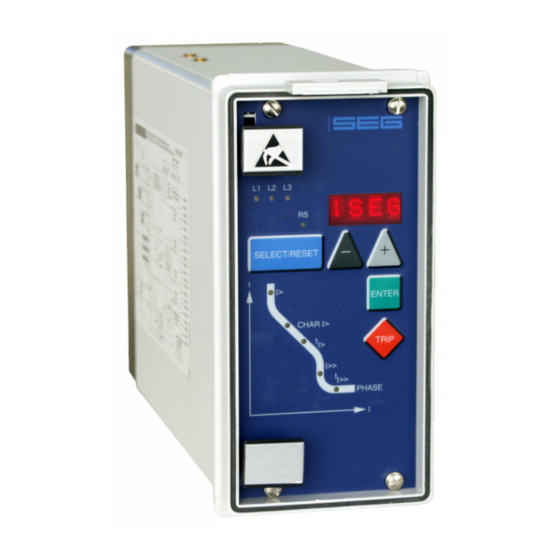
- Page 1 MANUAL HighTECH Line PROTECTION TECHNOLOGY MADE SIMPLE MRI1IU VOLTAGE CONTROLLED TIME-OVERCURRENT RELAY VOLTAGE CONTROLLED TIME-OVERCURRENT RELAY Original document English Revision: A...
-
Page 2: Table Of Contents
Contents Introduction and application Relay testing and commissioning Power-On Testing the output relays and LEDs Features and characteristics Checking the set values Secondary injection test Design 6.4.1 Test equipment Connections 6.4.2 Example of test circuit 3.1.1 Analogue input circuits 6.4.3 Checking the input circuits and 3.1.2 Output relays... -
Page 3: Introduction And Application
Introduction and application Features and characteristics • Digital filtering of the measured values by using dis- The digital multifunctional relay MRI1-IU is an universal protection device for alternators and other equipment. crete Fourier analysis to suppress the high frequence It provides the following functions: harmonics and DC components induced by faults or •... -
Page 4: Design
Design Connections Figure 3.1: Connection diagram 3.1.1 Analogue input circuits 3.1.3 Blocking input The protection unit receives the analogue input signals The blocking functions adjusted before will be blocked of the phase currents IL1 (B3-B4), IL2 (B5-B6), IL3 B7- if an auxiliary voltage is connected to (terminals) B8)), as well as the phase voltages via isolated input D8/E8. -
Page 5: Leds
LEDs Working principle The LEDs left from the display are partially bi-coloured, Analogue circuits the green indicating measuring, and the red fault indi- cation. The incoming currents from the main current transform- ers on the protected object are converted to voltage The LED marked with letters RS lights up during setting signals in proportion to the currents via the input trans- of the slave address of the device for serial data com-... -
Page 6: Digital Circuits
Switching-over at undervoltage (Example ISL = 0.5) Digital circuits The essential part of the MRI1-IU relay is a powerful microcontroller. All of the operations, from the ana- logue digital conversion to the relay trip decision, are carried out by the microcontroller digitally. The relay program is located in an EPROM (Electrically- Programmable-Read-Only-Memory). -
Page 7: Operation And Setting
Operation and setting Display Function Display shows Pressed push button Corresponding LED Normal operation Actual measured values, <SELECT/RESET> L1, L2, L3, U Measured operating values: one time for each <SELECT/RESET> Measuring range overflow max. L1, L2, L3, U <SELECT/RESET> Setting values: Current settings I >;... -
Page 8: Setting Procedure
Setting procedure 5.2.2 Time current characteristics for phase overcurrent element After push button <SELECT/RESET> has been pressed, (CHAR I>) always the next measuring value is indicated. Firstly the operating measuring values are indicated and then By setting this parameter, one of the following the setting parameters. -
Page 9: Reset Setting For Inverse Time Tripping
5.2.4 Reset setting for inverse time 5.2.7 Undervoltage set reference value tripping characteristics in the When adjusting the undervoltage switching point a phase current path value in volt is shown on the display. The LED U flashes red during the setting. To ensure tripping, even with recurring fault pulses shorter than the set trip delay, the reset mode for in- verse time tripping characteristics can be switched... -
Page 10: Blocking The Protection Functions And Assignment Of The Output Relays
5.2.10 Blocking the protection functions and assignment of the output relays The relays are assigned as follows: LEDs I>, I>>, are Blocking the protection functions: two-coloured and light up green when the output re- The blocking function of the MRI1-IU can be set ac- lays are assigned as alarm relays and red as trip- cording to requirement. -
Page 11: Indication Of Measuring Values And
Indication of measuring values Reset and fault data Unit MRI1-IU has the following three possibilities to re- set the display of the unit as well as the output relay at 5.3.1 Indication of measuring values jumper position J3=ON. The following measuring quantities can be indicated on the display during normal service: Manual Reset •... -
Page 12: Relay Testing And Commissioning
Checking the set values Relay testing and commissioning By repeatedly pressing the push button <SELECT>, all The test instructions following below help to verify the protection relay performance before or during commis- relay set values may be checked. Set value modifica- tion can be done with the push button <+><->... -
Page 13: Example Of Test Circuit
6.4.2 Example of test circuit for MRI1-IU relays without directional feature The three phase voltage should be adjustable within For testing MRI1-IU relays current and voltage input the effective operating range of the undervoltage ele- signals are required. Figure 6.1 shows an example of ment and have a phase relationship apart from 120°. -
Page 14: Checking The Operating And Resetting
6.4.4 Checking the operating and 6.4.6 Checking the high set element resetting values of the relay under of the relay normal and low voltage Set a current above the set operating value of I>>. In- ject the current instantaneously and check that the Apply three phase voltages 5% above the undervolt- age set value and inject a current which is less than alarm output relay I>>... -
Page 15: Primary Injection Test
Primary injection test Maintenance Generally, a primary injection test could be carried out Maintenance testing is generally done on site at regu- in the similar manner as the secondary injection test lar intervals. These intervals vary among users depend- described above. With the difference that the pro- ing on many factors: e.g. -
Page 16: Technical Data
Technical data Measuring input circuits Rated data: Nominal current I 1A or 5A Nominal voltage U 100 V, 230 V, 400 V Nominal frequency f 50 Hz; 60 Hz adjustable Power consumption in current circuit: at I = 1 A 0.2 VA at I = 5 A... -
Page 17: Setting Ranges And Steps
Setting ranges and steps 7.3.1 Definite time overcurrent protection relay Setting range Step Tolerance ±3 % from set value or 0.2...4.0 x I 0.05; 0.1 x I min. ±1 % In ±3 % or ±10 ms tI> 0.03 - 260 s 0.01;... -
Page 18: Inverse Time Characteristics
Inverse time characteristics 1000 1000 I> 10.0 I> t[s] t[s] 10.0 0.05 0.05 5 6 7 8 9 10 5 6 7 8 9 10 Figure 7.1: Normal Inverse Figure 7.3: Very Inverse 1000 I> 0.02 t[s] t[s] I> > 10.0 0.03 I>>... -
Page 19: Order Form
Order form Voltage controlled time overcurrent relay MRI1- 3-phase current I>, I>> Rated current Voltage dependent tripping characteristic Rated voltage 100 V 230 V 400 V Housing (12TE) 19“-rack Flush mounting Setting of code jumpers Code jumper Default setting Actual setting Default setting Actual setting Default setting Actual setting Plugged no function Not plugged... - Page 20 Setting list MRI1 Note ! All settings must be checked at site and should the occasion arise, adjusted to the object/item to be protected. Project: SEG job.-no.: Function group: = Location: + Relay code: - Relay functions: Password: Date: Setting of the parameters...
- Page 21 TD_MRI1-IU_05.04_GB...
- Page 22 SEG Electronics GmbH reserves the right to update any portion of this publication at any time. Information provided by SEG Electronics GmbH is believed to be correct and reliable. However, SEG Electronics GmbH assumes no responsibility unless otherwise expressly undertaken.
Need help?
Do you have a question about the HighTECH Line MRI1IU and is the answer not in the manual?
Questions and answers