Sign In
Upload
Manuals
Brands
Seg Manuals
Relays
MRM3
Seg MRM3 Manuals
Manuals and User Guides for Seg MRM3. We have
2
Seg MRM3 manuals available for free PDF download: Manual
Seg MRM3 Manual (70 pages)
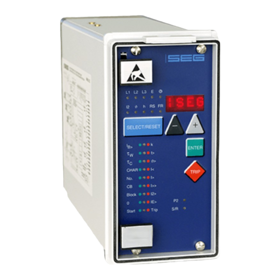
MOTOR PROTECTION RELAY
Brand:
Seg
| Category:
Relays
| Size: 2 MB
Table of Contents
Table of Contents
3
Introduction and Application
6
Characteristics and Features
7
Design
8
Connections
8
Analog Inputs
9
Output Relays
9
Digital Inputs
10
Low/High Range of the Digital Inputs
10
Front Plate
11
Indicating Leds
12
Adjusting Leds
12
Analog Part
12
Digital Part
13
Working Principle
14
Start Recognition
14
Criteria for Blocking the Start
16
Starting Time
18
Thermal Image
18
Requirement on the Main Current Transformers
19
Operation and Adjustments
20
Displayed Text for Parameter Settings
20
Setting Procedure
21
System Parameters
21
Presentation of Measuring Values as Primary Quantities on the Display
21
Prim Phase)
21
Rated -Frequency
21
Operating Hour Meter (H)
21
Number of Motor Starts (No.)
21
Indication of Pickup
21
Parameter Set Changeover Switch (P2)
22
Protection Parameters
22
Thermal Overload Protection (K X IB)
22
Warning/Tripping with Thermal Overload
22
Tripping Delay for Thermal Overload
22
Heating Period Constant
22
W and Cooling-Down Time Factor C
22
T2X and T6X Minimal Trip Time During the Starting Process
23
Phase Undercurrent Element (I<)
23
Phase over Current Element (I>)
23
Trip Characteristics for the Phase over Current Element (I>+CHAR)
23
Tripping Time or Time Factor for the Phase over Current Element (I>+T>)
24
Reset Mode for the Trip Characteristics in the Phase Current Path (I>+Char+T>)
24
Phase Short-Circuit Trip (I>>) and (I>>+Start)
24
Negative Phase Sequence
25
Earth Fault Element (IE>)
25
Switching over Warning/Tripping
25
Trip Characteristics for the Earth-Fault Element (IE>+CHAR)
25
Tripping Time or Time Factor for the Earth Fault Element (Ie>+T>)
26
Reset Time for the Earth Fault Element (Ie>+Char+T>)
26
Tripping Time for the CB Failure-Protection (Cb+T>)
26
External Trip (Delayed)(Trip+T>)
26
Trip Blocking in Case of Excessive Phase Current (Trip+Block)
26
Start Supervision
27
Duration of a Start Cycle (No.+Start)
27
Number of Starts Per Cycle (No.+Start)
27
Start Blocking Time (Start+Block+T>)
27
Characteristic for the Starting Time
27
Rated Starting Current I_Start
27
Maximal Start Time (Start+T>)
28
Start-Up Recognition Time or Motor Running Time
28
Stopping Time
28
Interface Parameters
28
Adjustment of the Slave-Address (RS)
28
Adjustment of the Baud-Rate (Only for Modbus Protocol)
28
Adjustment of the Parity (Only for Modbus-Protocol)
28
Recorder (FR)
29
Fault Recorder or Disturbance Recorder
29
Number of Fault Recordings
30
Adjustment of the Trigger Event
30
Vor )
30
Pre-Trigger Time
31
Setting of the Clock
31
Additional Functions
32
Blocking of the Protective Functions
32
Allocation of the Reset Functions
33
Allocation of the Output Relays
34
Measuring Value and Fault Indications
36
Measuring Value Indications
36
Units of the Displayed Measuring Values
36
Indication of the Fault Data
36
Fault Memory
37
Reset
38
Erasure of the Fault Memory
38
Reset of the Thermal Memory
38
Digital Inputs
39
Parameter Set Changeover Switch
39
External Trigger of the Fault Recorder
39
Recognition of "Motor Running" Condition
39
Undelayed External Trip
39
Delayed External Trip
39
Notes on Relay Tests and Commissioning
40
Connection of the Auxiliary Voltage
40
Testing of Output Relays and Leds
40
Test Circuit for MRM3-2
41
Checking of Input Circuits and of the Measuring Values
41
Testing the START-STOP-RUNNING Recognition
41
Testing the Pick-Up and Disengaging Values
42
Testing the Maximum Starting Time
42
Testing the Thermal Image
42
Testing the Control Inputs
42
Testing the CB Failure Protection
42
Primary Test
43
Maintenance
43
Technical Data
44
Measuring Input
44
Common Data
44
Setting Ranges and Steps
45
System Parameter
45
Time over Current Protection
46
Load Unbalance Protection
48
Earth Fault Protection
49
Circuit Breaker Failure Protection
50
External Trip Delay
50
Trip Blocking Beginning with the Adjusted Rated Current
50
Start Parameter
51
Interface Parameter
52
Fault Recorder Parameter
52
Tripping Characteristics
53
Tripping Characteristic for Max. Starting Time
53
Thermal Image
54
Initial Load Factor
54
Tripping of T2X and T6X - Times
55
Inverse Time over Current Protection
56
Trip Characteristics
57
Inverse Time Characteristic for Load Unbalance
61
Output Relays
61
Order Form
62
Advertisement
Seg MRM3 Manual (46 pages)
Motor Protection Relay
Brand:
Seg
| Category:
Relays
| Size: 1 MB
Table of Contents
Table of Contents
2
Introduction and Application
4
Characteristics and Features
4
Design
5
Connections
5
Analog Inputs
6
Output Relays
6
Digital Inputs
6
Low/High Range of the Digital Inputs
6
Front Plate
7
Indicating Leds
7
Adjusting Leds
7
Analog Part
8
Digital Part
8
Working Principle
9
Start Recognition
9
Criteria for Blocking the Start
10
Thermal Image
12
Requirement on the Main Current
12
Transformers
12
Operation and Adjustments
13
Settting Procedure
14
System Parameters
14
Presentation of Measuring Values as
14
Primary Quantities on the Display
14
(I Prim Phase)
14
Rated -Frequency
14
Operating Hour Meter (H)
14
Number of Motor Starts (No.)
14
Parameter Set Changeover Switch (P2)
14
Protection Parameters
15
Thermal Overload Protection
15
B )
15
Heating Period Constant Τ W and
15
Cooling-Down Time Factor Τ C
15
T2X and T6X Minimal Trip Time During
15
Phase Undercurrent Element (I<)
15
Phase Overcurrent Element (I>)
15
Trip Characteristics for the Phase over
15
Current Element (I>+CHAR)
15
Reset Mode for the Trip Characteristics
16
Phase Short-Circuit Trip (I>>) and (I>>+Start)
16
Negative Phase Sequence
16
Earth Fault Element
16
Element (I E >+CHAR)
17
Reset Time for the Earth Fault Element
17
Tripping Time for the CB Failure-Protection (Cb+T>)
17
External Trip (Delayed) (Trip+T>)
17
Trip Blocking in Case of Excessive Phase
17
Start Supervision
17
Duration of a Start Cycle (No.+Start)
17
Number of Starts Per Cycle (No.+Start)
17
Start Blocking Time (Start+Block+T>)
18
Maximal Start Time (Start+T>)
18
Interface Parameters
18
Adjustment of the Slave-Address (RS)
18
Adjustment of the Baud-Rate
18
Adjustment of the Parity
18
Fault Recorder (FR)
18
Fault Recorder
18
Number of Fault Recordings
19
Adjustment of the Trigger Event
19
Pre-Trigger Time
19
Setting of the Clock
19
Additional Functions
20
Blocking of the Protective Functions
20
Allocation of the Reset Functions
21
Allocation of the Output Relays
22
Measuring Value and Fault Indications
23
Measuring Value Indications
23
Units of the Displayed Measuring Values
24
Indication of the Fault Data
24
Fault Memory
24
Reset
25
Erasure of the Fault Memory
25
Reset of the Thermal Memory
25
Digital Inputs
25
Parameter Set Changeover Switch
25
External Trigger of the Fault Recorder
25
Recognition of "Motor Running
25
Condition
25
Undelayed External Trip
25
Delayed External Trip
25
Advertisement
Related Products
Seg HighTECH MRR1
Seg HighTECH Line MRI1IU
Seg HighTECH MRU3-2
Seg HighTECH Line MRN3-3
Seg High Tech MRI3-ITE
Seg MRIK3-C
Seg MRN3
Seg MRU3-1
Seg MRF3
Seg MRP2
Seg Categories
Relays
LED TV
LCD TV
Protection Device
TV
More Seg Manuals
Login
Sign In
OR
Sign in with Facebook
Sign in with Google
Upload manual
Upload from disk
Upload from URL