Azoteq IQ Switch ProxFusion Series Setup Manual
Hide thumbs
Also See for IQ Switch ProxFusion Series:
- Quick start manual (15 pages) ,
- User manual (15 pages) ,
- User manual (8 pages)
Table of Contents
Advertisement
Quick Links
The purpose of this document is to guide the designer in setting up the IQS7223C for capacitive
proximity detection using the ProxBox demonstration device.
Contents
2.1
Step 1: GUI Software Installation . . . . . . . . . . . . . . . . . . . . . . . . . . . . .
2.2
Step 2: Hardware Connections . . . . . . . . . . . . . . . . . . . . . . . . . . . . . .
2.3
Step 3: PC Connection . . . . . . . . . . . . . . . . . . . . . . . . . . . . . . . . . . .
2.4
Step 4: Initiate DUT Communication (Streaming) . . . . . . . . . . . . . . . . . . . .
2.5
Step 5: DUT Start-up and Initialisation . . . . . . . . . . . . . . . . . . . . . . . . . .
2.6
Step 6: Import Device Configuration (Optional) . . . . . . . . . . . . . . . . . . . . .
2.7
Step 7: Export Device Configuration (Optional) . . . . . . . . . . . . . . . . . . . . .
4.1
Channel Setup . . . . . . . . . . . . . . . . . . . . . . . . . . . . . . . . . . . . . . .
4.2
Sensitivity Adjustment . . . . . . . . . . . . . . . . . . . . . . . . . . . . . . . . . . .
4.3
Threshold Adjustment . . . . . . . . . . . . . . . . . . . . . . . . . . . . . . . . . . .
4.4
Noise Suppression . . . . . . . . . . . . . . . . . . . . . . . . . . . . . . . . . . . . .
Copyright © Azoteq 2023
All Rights Reserved
IQ Switch
®
ProxFusion
IQS7223C Setup Guide
IQS7223C Setup Guide
Revision v1.0.0
®
Series
2
2
2
3
4
5
5
6
6
8
11
12
13
14
15
15
16
Page 1 of 17
June 2023
Advertisement
Table of Contents

Subscribe to Our Youtube Channel
Related Manuals for Azoteq IQ Switch ProxFusion Series


Summary of Contents for Azoteq IQ Switch ProxFusion Series
-
Page 1: Table Of Contents
Noise Suppression ........5 Conclusion 6 Revision History Copyright © Azoteq 2023 IQS7223C Setup Guide Page 1 of 17 All Rights Reserved Revision v1.0.0... -
Page 2: Introduction
GUI software to address their unique application. Furthermore, the scope of this document is limited to the configuration of the IQS7223C using the appropriate and latest Azoteq IQS7223C GUI PC software. For guidelines on the hardware and electrode design, please refer to the applicable application notes. -
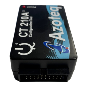
Page 3: Step 2: Hardware Connections
® ProxFusion Series 2.2 Step 2: Hardware Connections Connect your PC to the Azoteq configuration debug and display tool CT210A using a standard USB- micro data cable. The device under test (DUT), being either an IQS7223C EV-kit or an application PCBA with the device and required passives mounted on, can be interfaced with a suitable 20-to-10- pin ribbon cable connection (or application-specific connections) as shown in the below picture. -
Page 4: Step 3: Pc Connection
Figure 2.5 below the CT210A connected was already up to date with the latest firmware and thus not requiring an update. Figure 2.5: CT210A Firmware Upgrader Copyright © Azoteq 2023 IQS7223C Setup Guide Page 4 of 17 All Rights Reserved Revision v1.0.0... -
Page 5: Step 4: Initiate Dut Communication (Streaming)
2.5 Step 5: DUT Start-up and Initialisation Click on ’ACK RESET’ as shown in Figure 2.7. Bars will appear on Channels 0, 1, 2 and 3: Copyright © Azoteq 2023 IQS7223C Setup Guide Page 5 of 17 All Rights Reserved Revision v1.0.0... -
Page 6: Step 6: Import Device Configuration (Optional)
Note: Only a single instance of the GUI software may run at any given moment and therefore, only one device can be streamed at a time. Opening multiple instances of the GUI (or other Azoteq PC software and tools) will lead to program and streaming malfunctions. - Page 7 ‘EXPORT H FILE’ button. Take care to save the new settings file with an appropriately descriptive name and file location as intended. Figure 2.9: Exporting a Defined Configuration Copyright © Azoteq 2023 IQS7223C Setup Guide Page 7 of 17 All Rights Reserved Revision v1.0.0...
-
Page 8: Gui Overview
It is advised that the user utilise the ‘USER SETTINGS’ interface as the primary configuration portal. Except for some settings described later in this document, the settings tree should not be used without the support of an Azoteq or distributor FAE. Copyright © Azoteq 2023... - Page 9 ∗ Power Mode. Active when power mode switches. ∗ Channel Filter-halt. Active when a channel enters or exits a filter halt state (indi- cated by a bar graph changing from green to blue). Copyright © Azoteq 2023 IQS7223C Setup Guide Page 9 of 17 All Rights Reserved Revision v1.0.0...
- Page 10 ∗ CH0 Activation. Active while CH0 is activated. ∗ CH1 Activation. Active while CH1 is activated. ∗ CH2 Activation. Active while CH2 is activated. ∗ CH3 Activation. Active while CH3 is activated. Copyright © Azoteq 2023 IQS7223C Setup Guide Page 10 of 17 All Rights Reserved Revision v1.0.0...
-
Page 11: Application Example
The sections that follow will elaborate on the relevant sensor settings that may be adjusted. As such, the reader is advised to load the predefined configuration settings as discussed in 2.6. Copyright © Azoteq 2023 IQS7223C Setup Guide Page 11 of 17 All Rights Reserved Revision v1.0.0... -
Page 12: Channel Setup
5. Rx Selection. The IQS7223C allows up to four pins (CRX0 to 3) to be selected as inputs. As per Figure 4.1, only CRX3 is used, and must therefore be selected. Figure 4.3: IQS7223C Channel Settings Window Copyright © Azoteq 2023 IQS7223C Setup Guide Page 12 of 17 All Rights Reserved Revision v1.0.0... -
Page 13: Sensitivity Adjustment
2. ATI Mode. This setting determines the mode of the ATI algorithm. It is recommended to have it set at ’Full’. Figure 4.4: IQS7223C ATI Adjustment Settings Copyright © Azoteq 2023 IQS7223C Setup Guide Page 13 of 17 All Rights Reserved Revision v1.0.0... -
Page 14: Threshold Adjustment
IQS7223C registers a user detection, which leads to the channel activation flag being set. A lower threshold value will increase the perceived sensitivity of the device. Figure 4.5: IQS7223C Threshold Adjustment Settings Copyright © Azoteq 2023 IQS7223C Setup Guide Page 14 of 17 All Rights Reserved Revision v1.0.0... -
Page 15: Noise Suppression
This document explained the general guidelines for streaming and testing the IQS7723C IC using the ProxBox keyboard device as an application example. For more detailed guidelines, please refer to the relevant application note and IQS7223C datasheet. Alternatively, please contact Azoteq for assistance. -
Page 16: Revision History
® IQ Switch ® ProxFusion Series 6 Revision History Release Date Comments v1.0 2023/06/23 Initial document released Copyright © Azoteq 2023 IQS7223C Setup Guide Page 16 of 17 All Rights Reserved Revision v1.0.0 June 2023... - Page 17 No licenses to patents are granted, implicitly, express or implied, by estoppel or otherwise, under any intellectual property rights. In the event that any of the abovementioned limitations or exclusions does not apply, it is agreed that Azoteq’s total liability for all losses, damages and causes of action (in contract, tort (including without limitation, negligence) or otherwise) will not exceed the amount already paid by the customer for the products.
Need help?
Do you have a question about the IQ Switch ProxFusion Series and is the answer not in the manual?
Questions and answers