Azoteq IQ Switch ProxFusion Series User Manual
Hide thumbs
Also See for IQ Switch ProxFusion Series:
- Setup manual (17 pages) ,
- User manual (15 pages) ,
- Quick start manual (15 pages)

Related Manuals for Azoteq IQ Switch ProxFusion Series


Summary of Contents for Azoteq IQ Switch ProxFusion Series
-
Page 1: Iqs72Xxxev01 User Guide
IQ Switch ® ProxFusion ® Series IQS72xxxEV01 USER GUIDE ® ® IQ Switch - ProxFusion Series Copyright © Azoteq (Pty) Ltd 2021. IQS72xxxEV01 User Guide Page 1 of 9 All Rights Reserved. Revision 2.0 August 2021... -
Page 2: Table Of Contents
IQS7211A STAMP ............................ 4 IQS7222A STAMP ............................ 5 IQS7222B STAMP ............................ 6 IQS7222C STAMP ............................ 7 REFERENCE DESIGNS ........................... 8 Copyright © Azoteq (Pty) Ltd 2021. IQS72xxxEV01 User Guide Page 2 of 9 All Rights Reserved. Revision 2.0 August 2021... -
Page 3: Introduction
USB support, along with the CT210A, (CT210A sold separately) and the relevant IQS72xxx software Graphical User Interface (GUI) available to download from the Azoteq website. The purpose of the IQS72xxxEV01 EV-Kit is to help application and development engineers in evaluating the range of IC’s included in this Kit and their capabilities. -
Page 4: Setting Up For The Iqs72Xxx Stamp
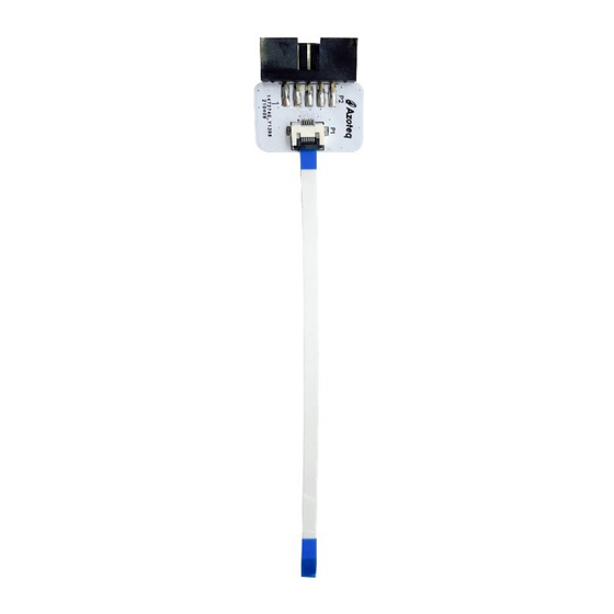
➢ Connect the 6-way cable into connector board on one end and on the stamp board at the other. ➢ Run the IQS72xxx GUI (latest version available from the www.azoteq.com website) IQS7211A Stamp ➢ Connect the CT210A to the connector board. -
Page 5: Iqs7222A Stamp
IQS7222A Stamp ➢ Connect the CT210A to the connector board. ➢ Connect connector board to IQS7222A stamp. ➢ Run IQS7222A GUI (available from Azoteq.com website) ➢ Click “Start Streaming” button ➢ GUI should look as follow. Copyright © Azoteq (Pty) Ltd 2021. -
Page 6: Iqs7222B Stamp
IQS7222B Stamp ➢ Connect the CT210A to the connector board. ➢ Connect connector board to IQS7222B stamp. ➢ Run IQS7222B GUI (available from Azoteq.com website) ➢ Click “Start Streaming” button ➢ GUI should look as follow. Copyright © Azoteq (Pty) Ltd 2021. -
Page 7: Iqs7222C Stamp
IQS7222C Stamp ➢ Connect the CT210A to the connector board. ➢ Connect connector board to IQS7222C stamp. ➢ Run IQS7222C GUI (available from Azoteq.com website) ➢ Click “Start Streaming” button ➢ GUI should look as follow. Copyright © Azoteq (Pty) Ltd 2021. -
Page 8: Reference Designs
IQ Switch ® ProxFusion ® Series Reference Designs Figure 7-1 IQS72xxx QFN20 Stamp Layout Copyright © Azoteq (Pty) Ltd 2021. IQS72xxxEV01 User Guide Page 8 of 9 All Rights Reserved. Revision 2.0 August 2021... - Page 9 Azoteq assumes no liability for any damages or injury arising from any use of the information or the product or caused by, without limitation, failure of performance, error, omission, interruption, defect, delay in operation or transmission, even if Azoteq has been advised of the possibility of such damages.
Need help?
Do you have a question about the IQ Switch ProxFusion Series and is the answer not in the manual?
Questions and answers