Pioneer DDJ-SR Service Manual
Dj controller
Hide thumbs
Also See for DDJ-SR:
- Quick start manual (68 pages) ,
- Operating instructions manual (34 pages) ,
- Operation manual (18 pages)
Table of Contents
Advertisement
Quick Links
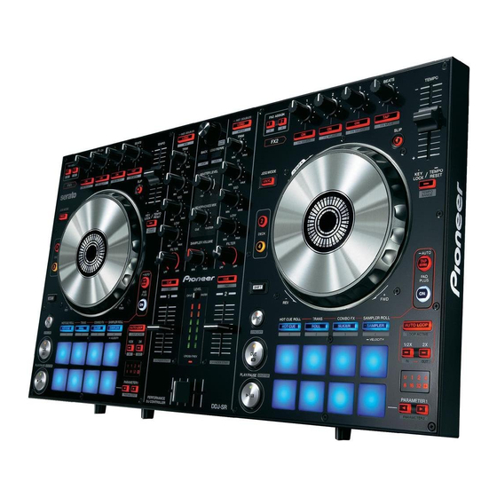
DJ Controller
DDJ-SR
THIS MANUAL IS APPLICABLE TO THE FOLLOWING MODEL(S) AND TYPE(S).
Model
Type
DDJ-SR
CKSUVYXE5
DDJ-SR
XECN5
PIONEER CORPORATION
PIONEER ELECTRONICS (USA) INC. P.O. Box 1760, Long Beach, CA 90801-1760, U.S.A.
PIONEER EUROPE NV Haven 1087, Keetberglaan 1, 9120 Melsele, Belgium
PIONEER ELECTRONICS ASIACENTRE PTE. LTD. 253 Alexandra Road, #04-01, Singapore 159936
PIONEER CORPORATION
Power Requirement
DC 5 V (USB-bus power only)
DC 5 V (USB-bus power only)
1-1, Shin-ogura, Saiwai-ku, Kawasaki-shi, Kanagawa 212-0031, Japan
2013
DDJ-SR
K-MZV NOV.
ORDER NO.
RRV4499
Remarks
2013 Printed in Japan
Advertisement
Table of Contents

Related Manuals for Pioneer DDJ-SR


Summary of Contents for Pioneer DDJ-SR
- Page 1 PIONEER CORPORATION 1-1, Shin-ogura, Saiwai-ku, Kawasaki-shi, Kanagawa 212-0031, Japan PIONEER ELECTRONICS (USA) INC. P.O. Box 1760, Long Beach, CA 90801-1760, U.S.A. PIONEER EUROPE NV Haven 1087, Keetberglaan 1, 9120 Melsele, Belgium PIONEER ELECTRONICS ASIACENTRE PTE. LTD. 253 Alexandra Road, #04-01, Singapore 159936...
-
Page 2: Table Of Contents
10.4 PANEL-L and R PCB ASSYS............................50 10.5 WAVEFORMS ................................52 11. PCB CONNECTION DIAGRAM ............................56 11.1 MIC and HEADPHONE PCB ASSYS .........................56 11.2 I/O PCB ASSY ................................58 11.3 MIXER and CROSS FADER PCB ASSYS........................60 11.4 PANEL-L and R PCB ASSYS............................62 12. PCB PARTS LIST ................................64 DDJ-SR... -
Page 3: Service Precautions
Chassis Assy side. double-back tape NITTO No. 500 (5 mm × 30 mm) NITTO No. 500 NITTO No. 500 NITTO No. 500 (5 mm × 40 mm) (5 mm × 80 mm) (5 mm × 40 mm) DDJ-SR... -
Page 4: About Demo Mode
LED illumination will start. To cancel this mode, operate any control or button of this unit. To disable Demo mode, change the setting in the settings of Utilities mode 1. (For details, refer to the operating instructions.) DDJ-SR... -
Page 5: Specifications
(408-SUB-132) Tolerable operating temperature......+5 °C to +35 °C Tolerable operating humidity....5 % to 85 % (no condensation) • Read Before Use (Important)/Quick Start Guide (DDJ-SR/CKSUVYXE5: 502-DDJSRA-3325A, 502-DDJSRA-3326A) Audio Section (DDJ-SR/XECN5: 502-DDJSRB-3327) Rated output level MASTER OUT 1 ............. 4.2 Vrms •... -
Page 6: Basic Items For Service
3.2 JIGS LIST Jigs List Jig Name Part No. Purpose of use / Remarks USB cable GGP1193 for PC connection Lubricants and Glues List Name Part No. Remarks Adhesive GYL1001 Refer to “7. DISASSEMBLY”. Grease GEM1096 Refer to “7. DISASSEMBLY”. DDJ-SR... -
Page 7: Pcb Locations
Description Part No. Mark No. Description Part No. LIST OF ASSEMBLIES MIC PCB ASSY 704-SR-A601 PANEL-L PCB ASSY 704-SR-A599 HEADPHONE PCB ASSY 704-SR-A600 PANEL-R PCB ASSY 704-SR-A598 I/O PCB ASSY 704-SR-A596 MIXER PCB ASSY 704-SR-A597 CROSS FADER ASSY 704-DJM250-A032 DDJ-SR... -
Page 8: Block Diagram
When ordering service parts, be sure to refer to "EXPLODED VIEWS and PARTS LIST" or "PCB PARTS LIST". The > mark found on some component parts indicates the importance of the safety factor of the part. Therefore, when replacing, be sure to use parts of identical designation. DDJ-SR... - Page 9 LED3 LED4 LED4 CN500 PANEL-L LED5 LED5 LED6 LED6 PCB ASSY PCB ASSY LED7 LED7 LED8 LED8 HEADPHONE PCB ASSY WL -A (WR- A) WL -A (704-SR-A600) WL -B (WR- B) WL -B LED- G LED- G DGND DGND DDJ-SR...
-
Page 10: Overall Block Diagram
FSR PAD * 8 AD * 8 VUSB IC16 TUSB3200 (12MHz or 48MHz) USB PortB LEVEL -5.46dB IC22 PCM1803 IC15 ADSP-BF592 (44.1K/24bit/512fs for A/D,D (I2S format for audio data) +20dB LEVEL +9.4dB -5.46dB IC23 IC900 IC900 PCM1803 MIC PCB ASSY DDJ-SR... - Page 11 Hz or 48MHz) LPF&. IC24 MASTER1 IC15 ADSP-BF592 CS4344 4.1K/24bit/512fs for A/D,D/A) BOOTH NJM4580 NJM4580 2S format for audio data) LPF&. IC25 BOOTH/MASTER2 (RCA) CS4344 24.576M NJM4580 HEADPHONE PCB ASSY LPF&. IC26 Headphone (32 ohm/6.3mm & 3.5mm) CS4344 NJM4556 DDJ-SR...
-
Page 12: Diagnosis
No UCOM (IC16) is defective. When you turned a rotary the parts mentioned above? Replace the I/O PCB Assy. Replace the I/O PCB Assy. selector, is the signal H? Rotary selector is defective. Replace the corresponding part. Replace the rotary selector. DDJ-SR... - Page 13 Cannot store user settings. The setting information is saved in IC19. No E2ROM (IC19) is defective. Are SCL and the SDA signals "H" or "L"? Replace the I/O PCB Assy. UCOM (IC20) is defective. Replace the I/O PCB Assy. DDJ-SR...
-
Page 14: Basic Operation Check Using Serato Dj
The operating environment of the PC required for installation of Serato DJ is shown below. • For the latest information on the required operating environment and compatibility as well as to acquire the latest operating system, refer to “Software Info” under “DDJ-SR” on the Pioneer DJ support site below. http://pioneerdj.com/support/ •... - Page 15 When Serato DJ is launched after it is installed, a yellow icon saying “BUY/ACTIVATE” might be displayed in the License panel on the right side of the Serato DJ screen. DDJ-SR users do not have to activate or buy Serato DJ. If you tick the check box of [DO NOT SHOW AGAIN] and click [Online], the icon will disappear thereafter.
- Page 16 Adjust [TRIM] so that the orange indicator on the channel level indicator lights at the peak level. 5 Turn the [MASTER LEVEL] control to adjust the audio level of the speakers. Monitoring sound with headphones Set the positions of the controls, etc., as shown below. DDJ-SR...
-
Page 17: Service Mode
The firmware version is displayed first. LED except it turn off. [Method to exit] Power-OFF [Note] When in this mode, the firmware version display appear first. In this mode, it does not work to communicate with computer via USB. In this mode, LED dimmer is not available. DDJ-SR... - Page 18 The firmware display the three-digit every 2 seconds in three times. The digits express by Headphone CUE/TAP buttons, and the numbers express by Level Indicator. X.XX X.XX X.XX 2 seconds later 2 seconds later 2 seconds later [Numerics expressed with the number of lit LEDs] DDJ-SR...
- Page 19 In case of the right parts, the right parts LED are lit. In case of the center parts, the right&left parts LED are lit. All buttons other than the Rotary selector, LED will light only while it is pressed. DDJ-SR...
- Page 20 In these type, the position is indicated in 12 steps from minimum to maximum. • • • • • • (*3) Channel fader In channel fader, the position is indicated in 13 steps from minimum to maximum. • • • • • • DDJ-SR...
- Page 21 When Rotary selectoris rotated, "LED BRIGHTNESS Mode" does not change. *As two LEDs of different colors each are embedded in the LOAD button and the HOT CUE, ROLL, SLICER, and SAMPLER buttons, LIGHTING COLOR mode can be used for failure diagnosis of each LED. DDJ-SR...
- Page 22 Volume value fluctuation check mode into Measurement mode Jog dial Rotation Time measurement mode [Method to enter] Press and hold the "SHIFT"+"DECK3" buttons then Power-ON. During this mode, "DECK 3" and "DECK 4" LEDs are lit. [Method to exit] Power-OFF DDJ-SR...
- Page 23 Display of the 2nd digit Display of the 3rd digit [Numerics expressed with the number of lit LEDs] If the measurement result is outside the specified range, check the amount of grease for the Jog dial and the chassis. DDJ-SR...
- Page 24 Get the A / D conversion value immediately after the start. It will be reference value. *A/D conversion value to be monitored is Raw data. 4 Start monitoring and later to monitor the A/D conversion value, do the following actions depending on its value with Master level indicator. DDJ-SR...
- Page 25 Rotary selector, and this value will be new reference value. 5. More time has elapsed, to maintain the above display 762 even though the value of the A/D. 6. More time has elapsed, Level indicator is lit as follows: become the value 764 of the A/D. DDJ-SR...
- Page 26 (right) deck are lit. on the left (right) deck is lit. • When the amount of force applied is medium (the converted value is "3"), Performance pad LEDs 1–4 on the left (right) deck are lit and the other LEDs are unlit. DDJ-SR...
-
Page 27: Disassembly
Knobs and Volumes Location 100-S1-3006 100-S1-3005 100-S1-3008 100-DDJLE-2944 100-S1-3010 ×14 ×2 ×7 ×2 ×1 White White White White Black Black Black Black Black 100-S1-3009 100-SR-3008 100-22-2824 ×2 ×1 ×3 White White Black Black Black DDJ-SR... - Page 28 • Bottom view • I/O PCB Assy (1) Remove the four screws. (602-B300-041) (2) Remove the Phone ground plate and MIC ground plate by removing the two screws. (602-DJ5500-452) ×2 ×2 • Bottom view MIC ground plate Phone ground plate DDJ-SR...
- Page 29 • Front view (3) Disconnect the one flexible cable. (CN701B) (4) Remove the HEADPHONE PCB Assy by Earth lead Earth lead removing the five screws. (602-DJ5500-452) Screw tightening order CN701B MIC PCB Assy HEADPHONE PCB Assy • Bottom view DDJ-SR...
- Page 30 • Bottom view (3) Remove the two Wheel Assemblies. Wheel Assy Wheel Assy [3] Each PCB Assemblies Note: When you remove each PCB Assemblies, it is not necessary to remove a jog dial section. (1) Remove the all knobs. ×27 DDJ-SR...
- Page 31 • Bottom view (2) Remove the two solders. (3) Remove the MIXER PCB Assy by removing the 20 screws. Remove the PANEL-L and R PCB Assemblies by removing the 52 screws. (602-SL24F-099) CN500 CN500 PANEL-R PCB Assy PANEL-L PCB Assy DDJ-SR...
- Page 32 (GYL1001) • Bottom view Adhesive (GYL1001) Chassis Assy Mixer fixed plate I/O PCB Assy MIXER PCB Assy • Bottom view Adhesive Adhesive (GYL1001) (GYL1001) CF fixed plate Adhesive (GYL1001) CROSS FADER PCB Assy MIC ground plate Phone ground plate DDJ-SR...
-
Page 33: Each Setting And Adjustment
4 When the firmware update process is complete, click the USB cable [OK] button. Note: Please note that if you fail to update, turn on the power of DDJ-SR again and start from Step 2 of the above Updating Procedures. DDJ-SR... - Page 34 How to check the Firmware Version For Windows For Mac From the [Start menu], Run [All Programs] → [Pioneer] → Open the Apple menu while pressing the option key, then [DDJ-SR] → [DDJ_SR Version Display Utility]. select “System Profiler” or “System Information.”...
-
Page 35: Items For Which User Settings Are Available
To enter Utilities mode 2, terminate the application, turn the unit OFF, then while holding the [SHIFT] and [PLAY/PAUSE] buttons on the right deck pressed, set the [ON/OFF] switch on the rear panel of the unit to ON. (For details, refer to the operating instructions of the unit.) DDJ-SR... - Page 36 Level 100 Slow Quick Performance pad 1 Performance pad 1 Performance pad 2 Performance pad 2 Performance pad 3 Performance pad 3 Performance pad 5 Performance pad 5 Performance pad 6 Performance pad 6 Performance pad 7 Performance pad 7 DDJ-SR...
- Page 37 DDJ-SR...
-
Page 38: Exploded Views And Parts List
Screws adjacent to b mark on product are used for disassembly. For the applying amount of lubricants or glue, follow the instructions in this manual. (In the case of no amount instructions, apply as you think it appropriate.) 9.1 PACKING SECTION DDJ-SR... - Page 39 Quick Start Guide 11 Read Before Use (Important)/ See Contrast table (2) Quick Start Guide 12 PE Bag 505-DJM250-014 (2) CONTRAST TABLE DDJ-SR/CKSUVYXE5 and XECN5 are constructed the same except for the following: DDJ-SR DDJ-SR Mark Symbol and Description /CKSUVYXE5 /XECN5...
-
Page 40: Exterior Section
9.2 EXTERIOR SECTION Wheel plate (NSP) Screw (NSP) Spring (NSP) Wheel & shaft Assy (NSP) Carbon pad (NSP) FSR fixed plate (NSP) DDJ-SR... - Page 41 : Accessories of VR (NSP) Bar-code (NSP) DDJ-SR...
- Page 42 87 Screw 602-QMX2BPM-322 42 -/- Button 100-SR-3054 88 Screw 602-QMX2BPM-322N 43 Auto Button 100-AUTO-3055 89 Screw 602-SA12-414 44 Cue Button 100-CUE-3055 90 Screw 602-DJ5500-452 45 Load Button 100-LOAD-3055 91 Screw 602-A700-494 92 Screw 602-PTP3012-571 93 Screw 602-ST306-728B 94 Screw 602-SW3008-737B DDJ-SR...
- Page 43 (2) CONTRAST TABLE DDJ-SR/CKSUVYXE5 and XECN5 are constructed the same except for the following: DDJ-SR DDJ-SR Mark Symbol and Description /CKSUVYXE5 /XECN5 Base 100-SRA-3052 100-SRB-3052 DDJ-SR...
-
Page 44: Schematic Diagram
C905 C907 R901 R907 10/25 9.1K R903 C901 C904 C908 220P 100/16 CHASSIS CHASSIS HEADPHONE PCB ASSY (704-SR-A600) JK 980 HEADP HONES(3.5m m) C980 C981 1500P 1500P CHASSIS HP L C982 JK 981 HP R HEADPHONE(6.3m m) C983 CHASSIS DDJ-SR... - Page 45 20K A R909 C912 R910 C911 2.2K MI CI N C909 10/25 C915 C913 CHASSIS SW950 AD3.3V CN701B REVERSE R950 CURVE C952 CN701A HP VR C.F .CUR C950 VR950 20K B C953 C951 HP LEVEL C955 VR951 20K B C954 DDJ-SR...
-
Page 46: I/O Pcb Assy
Bead TPS54232 Layout Rule , Please consult the attachment (TPS54232-Layout.pdf) The > mark found on some component parts indicates the importance of the safety factor of the part. Therefore, when replacing, be sure to use parts of identical designation. DDJ-SR... - Page 47 IC7B 470P C214 C253 R239 R243 4556 R253 R255 3.3K 6.8K R247 47/16 C215 22,1/4W 10,1/4W 3.3,F RN 1/4W 470/10 WR- A R287 WR- B 10/25 LED- G C222 180P DGND R245 C108 C109 R241 2SD2704K MUTE 1SS355 150K DDJ-SR...
-
Page 48: Mixer And Cross Fader Pcb Assys
10.3 MIXER and CROSS FADER PCB ASSYS CN701B DDJ-SR... - Page 49 CN1A MIXER PCB ASSY (704-SR-A597) CROSS FADER PCB ASSY (704-DJM250-A032) DDJ-SR...
-
Page 50: Panel-L And R Pcb Assys
10.4 PANEL-L and R PCB ASSYS DDJ-SR... - Page 51 PANEL-L PCB ASSY (704-SR-A599) PANEL-R PCB ASSY (704-SR-A598) CN2A (F) CN3A (G) DDJ-SR...
-
Page 52: Waveforms
C4 + side (D5V) C35 + side (A5V) IC16 pins 51, 50 C16 (DA3.3V) C36 + side (A3.3V) SELECT SW pin (AD) IC21 pins 7, 8 C17 (AD5V) TACT SW pin CN2B pins 31, 32 IC5 pins 1, 7 (1 kHz IN) DDJ-SR... - Page 53 IC24 pin 3 (LRCK) IC25 pin 1 (BOT) IC7 pins 1, 7 (1 kHz IN) IC26 pin 4 (SCK) IC24 pin 4 (SCK) IC25 pin 2 (BCK) IC26 pins 7, 10 (1 kHz IN) Q35 to Q38 base (-6V) DDJ-SR...
- Page 54 IC3 pin 1 (1 kHz IN) IC23 pin 15 (SCK) IC23 pin 1 (1 kHz IN) IC23 pin 10 (LRCK) IC23 pin 11 (BCK) IC23 pin 12 (MIC) DDJ-SR...
- Page 55 DDJ-SR...
-
Page 56: Pcb Connection Diagram
11. PCB CONNECTION DIAGRAM 11.1 MIC and HEADPHONE PCB ASSYS SIDE A MIC PCB ASSY SIDE B MIC PCB ASSY IC900 DDJ-SR... - Page 57 1. The parts mounted on this PCB include all necessary parts for several destinations. SIDE A For further information for respective destinations, be sure to check with the schematic diagram. SIDE B SIDE B P.C.Board Chip Part HEADPHONE PCB ASSY CN701A DDJ-SR...
-
Page 58: I/O Pcb Assy
11.2 I/O PCB ASSY SIDE A 34 35 CN2B CN2A CN1A SIDE B CN2A CN1A DDJ-SR... - Page 59 SIDE A 9 30 I/O PCB ASSY IC16 Q25-Q28 IC27 IC15 IC16 IC25 IC22 IC18 IC24 IC19 IC10 IC23 IC20 IC21 Q35-Q38 IC26 IC14 CN1B CN2C CN1A CN3A SIDE B I/O PCB ASSY CN1A CN3A IC12 IC11 IC13 DDJ-SR...
-
Page 60: Mixer And Cross Fader Pcb Assys
11.3 MIXER and CROSS FADER PCB ASSYS SIDE A SIDE A MIXER PCB ASSY W700 CN01 (SIDE B) CROSS FADER PCB ASSY DDJ-SR... - Page 61 SIDE B SIDE B MIXER PCB ASSY IC700 IC701 CN1A Q700-Q702 CN701B (SIDE A) W700 CN01 CROSS FADER PCB ASSY DDJ-SR...
-
Page 62: Panel-L And R Pcb Assys
11.4 PANEL-L and R PCB ASSYS SIDE A SIDE A PANEL-L PCB ASSY PANEL-R PCB ASSY CN500 DDJ-SR... - Page 63 SIDE B SIDE B PANEL-L PCB ASSY PANEL-R PCB ASSY IC500 Q506 Q507 IC501 Q500-Q505 IC502 CN500 CARBON PAD DDJ-SR...
-
Page 64: Pcb Parts List
C 93,94,120-124,134,135,144-148 413-DCM280-773 CAPACITORS C 154,155,187,188,208,209,224 413-DCM280-773 C 950,952-955,982,983 413-DCM280-773 C 225,230,259,261,262,266-283 413-DCM280-773 C 53,265 413-MC6000-1180 I/O PCB ASSY C 113 413-007USB-828 C 2,33-35,63,64,96,167,168 413-CDVD2001-265 SEMICONDUCTORS C 210,213,214,236-239 413-CDVD2001-265 Q 23-28,31-38 416-3000-378 Q 4,22,39 416-CTB200-166 413-DV300-5156 Q 21 416-HDJ9700-210 DDJ-SR... - Page 65 C 500, 533 413-CDVD2001-265 SEMICONDUCTORS C 532 413-SPPW3-235 Q 506,507 416-CTB200-166 C 501-507,514,515,529-531,535,536 413-DCM280-773 Q 500-505 416-MC6000-374 D 520-527 410-S1-421 D 530 410-S1-422 D 550 410-SR-437 D 548,549 410-HDJ2000-162T D 502,503 417-HDJ2000-411 D 554-579 414-CD1000-075A D 500,501 414-RMP3-285 D 512-519 410-CDI600-357T DDJ-SR...
Need help?
Do you have a question about the DDJ-SR and is the answer not in the manual?
Questions and answers