
Related Manuals for Comelit UT8020


Summary of Contents for Comelit UT8020
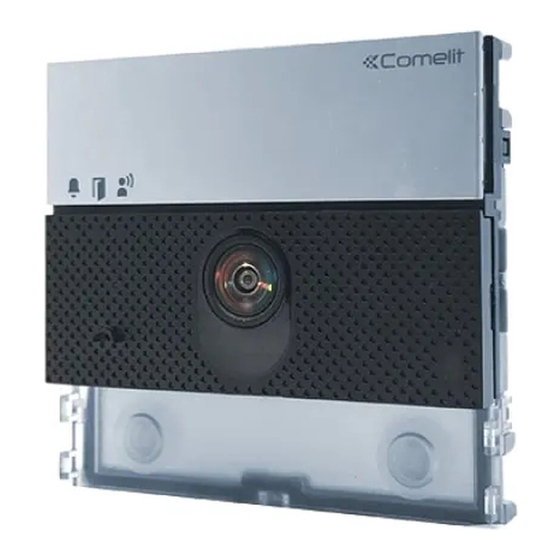
- Page 1 TECHNICAL MANUAL Ultra audio/video module, IP (ViP) system Art. UT8020 Passion.Technology.Design.
-
Page 2: Warning
• any purpose other than the intended use, • failure to observe the indications and warnings contained in this Manual / Instruction sheet. Comelit Group S.p.A. reserves the right to change the information provided in this Manual / Instruction Sheet at any time and without prior notice. -
Page 3: Table Of Contents
Table of contents Warning .................... 2 Description ..................4 UT8020 ......................4 Notes for the installer..............6 Technical specifications ..............7 Installation ..................8 Flush-mounted installation composition table ........8 Surface-mounted installation composition table ........9 Flush-mounted installation ............10 Removing nameplates (2A) / module (2B) ..........11 Installation with side-by-side boxes .............12... -
Page 4: Description
Description UT8020 Audio/video module for Ultra entrance panel, IP (ViP) system. Twilight sensor for automatic nameplate backlighting power-off during daytime hours. Omnidirectional digital microphone and double loudspeaker for high-fidelity audio. Wide-angle 2 Megapixel colour video camera (field of vision: 160° horizontal, 90° vertical). - Page 5 1. Indicator LEDs 7. Terminal block for connection: calling (green) RTE programmable input: RTE (local system busy (red) lock-release input), DO (door open first startup or restart (flashing red) indication), Activate output, Priority call or Call user lock-release enabled GND SE- RTE and door lock input reference communication enabled negative SE+ electric door lock connection...
-
Page 6: Notes For The Installer
Notes for the installer 90° 90° 90° 50 cm 50 cm 50 cm 570 cm 160° The camera must not be installed in front of light sources, or in places where the filmed subject is against the light. In dim environments, we recommend additional lighting is provided. -
Page 7: Technical Specifications
Technical specifications GENERAL DATA Type Modular Product height (mm) Product width (mm) Product depth (mm) Product colour Black RAL9005, Transparent, Aluminium Material Polycarbonate, Aluminium alloy Flush mounting Yes, with specific accessory Surface mounting Yes, with specific accessory COMPATIBLE SYSTEMS AUDIO SPECIFICATIONS Microphone MEMS digital audio sensor, omnidirectional Loudspeaker... -
Page 8: Installation
Installation The entrance panel is available in flush-mounted or surface-mounted variants: Flush-mounted installation composition table A = Flush-mounted box B = Rain shield C = Flush-mounted module holder with finishing frame 3110/1 3110/2 3110/3 3110/4 3110/1A 3110/2A 3110/3A 3110/4A UT9181 UT9182 UT9184H UT9183... -
Page 9: Surface-Mounted Installation Composition Table
Surface-mounted installation composition table A = Rain shield B = Surface-mounted housing with frame UT9191 UT9192 UT9194H UT9193 UT9196 UT9199 UT9194 UT9198 UT9171 UT9172 UT9174H UT9173 UT9176 UT9179 UT9174 UT9178 Optional... -
Page 10: Flush-Mounted Installation
Flush-mounted installation Optional Optional BLACK... -
Page 11: Removing Nameplates (2A) / Module (2B)
CLACK! CLACK! CLACK! CLACK! CLACK! CLACK! The button has a nameplate which can be written on (A); alternatively, an adhesive label can be applied (B). The total thickness of the nameplate + adhesive label MAX 0,2 mm must not exceed 0.2 mm. You can visit the website pro.comelitgroup.com to download the PDF to print the entrance panel name cards, using the pre- cut sheets (C) available in our catalogue (Art. -
Page 12: Installation With Side-By-Side Boxes
Installation with side-by-side boxes Before installing the boxes in the wall, fit the spacers. -
Page 13: Wall-Mounted Installation
Wall-mounted installation Optional Optional BLACK... -
Page 14: Removing Nameplates (2A) / Module (2B)
CLACK! CLACK! CLACK! CLACK! CLACK! CLACK! The button has a nameplate which can be written on (A); alternatively, an adhesive label can be applied (B). The total thickness of the nameplate + adhesive label MAX 0,2 mm must not exceed 0.2 mm. You can visit the website pro.comelitgroup.com to download the PDF to print the entrance panel name cards, using the MAX 0,2 mm... -
Page 15: Installation With Side-By-Side Boxes
Installation with side-by-side boxes... -
Page 16: Connections
BLUE & WHITE BLUE ORANGE WHITE ORANGE GREEN WHITE GREEN TX TX RX RX NO NC UT8020 UT9200 (MAX 10) Max 20 m. Local door-opener button. Connection with power supply from standard POE switch STANDARD BROWN & WHITE BROWN SWITCH BLUE &... -
Page 17: Connection With Separate Power Supply
1596B 1595 120-240 V 120-230 V TX TX RX RX TX TX RX RX NO NC UT8020 UT9200 UT8020 UT9200 (MAX 30) (MAX 15) Max 20 m. Local door-opener button. Connection with separate power supply and non-POE switch NON POE... -
Page 18: Variant For Using The External Entrance Panel Relay
Variant for using the external entrance panel relay 12V/24V AC-DC TX TX RX RX NO NC 4A MAX UT8020 UT9200 Variant with safety door lock 12/24V AC/DC TX TX RX RX NO NC UT8020 UT9200... -
Page 19: Module Connection
Module connection Maximum power available for the modules depending on the type of power supply. Power supply Maximum power available [W] Standard PoE 5,5 PoE from 1440 5,5 1595 7.5 1596B 15 power supply from floor distribution unit Art. 1440 or power supply with additional power supply unit Art. -
Page 20: Connection Of Button Modules Art. Ut9200
WHITE ORANGE GREEN WHITE GREEN TX TX RX RX NO NC BLACK UT8020 UT9200 MAX 10 Max 20 m. Local door-opener button. Max 10 modules (Max 30 modules with additional power supply, see “Connection with separate power supply”). Connection of Touchscreen module Art. UT9270... -
Page 21: Connection Of Touchscreen Module Art. Ut9270 With Additional Power Supply Unit
1596B 1595 120-230 V 120-240 V TX TX RX RX TX TX RX RX NO NC UT8020 UT8020 UT9270 UT9270 Max 20 m. Local door-opener button. Connection of number keypad module Art. UT9279M 1440 1441 BROWN & WHITE BROWN BLUE & WHITE BLUE... -
Page 22: Programming
Programming To perform programming correctly, proceed as follows: Address the button modules (see “Address button modules”) Configure the ViP address for the UT8020 module via ViP Manager (see“Programming via ViP Manager”) III. Program the ViP call addresses via ViP Manager (see“Programming via ViP... -
Page 23: Adjusting The Brightness Of The Button Leds
Adjusting the brightness of the button LEDs 1. Press the button for 3 sec., until you hear a beep. Release the button. » if the procedure was completed successfully, you will hear a confirmation tone; the red LED flashes and the button backlighting comes on. -
Page 24: Reset To Factory Values
10 sec 10'' Connection distances If Art. UT8020 is powered directly from third-party standard POE switches, the maximum distance is reduced to 100 m. 6802W 6722W 6702W 6602W... -
Page 25: Programming Via Vip Manager
Programming via ViP Manager All device configurations (with the exception of button module addressing) can be carried out via PC and ViP Manager software, which is available to download free of charge from the website pro.comelitgroup.com. For example: • programming call addresses for the buttons •... - Page 26 CERTIFIED MANAGEMENT SYSTEMS w w w . c o m e l i t g r o u p . c o m Via Don Arrigoni, 5 - 24020 Rovetta (BG) - Italy...
Need help?
Do you have a question about the UT8020 and is the answer not in the manual?
Questions and answers