Comelit Ultra Simplebus2 Technical Manual
Audio module
Hide thumbs
Also See for Ultra Simplebus2:
- Technical manual (20 pages) ,
- Technical manual (39 pages) ,
- Technical manual (30 pages)

Subscribe to Our Youtube Channel
Related Manuals for Comelit Ultra Simplebus2


Summary of Contents for Comelit Ultra Simplebus2
- Page 1 TECHNICAL MANUAL MYCOMELIT: THE APP FOR PROFESSIONALS MYCOMELIT, L'APP PER IL PROFESSIONISTA FREE DOWNLOAD Ultra Simplebus2 audio module art. UT2010, UT2010B, UT2010W...
-
Page 2: Warning
• any purpose other than the intended use, • failure to observe the indications and warnings contained in this Manual / Instruction sheet. Comelit Group S.p.A. reserves the right to change the information provided in this Manual / Instruction Sheet at any time and without prior notice. -
Page 3: Table Of Contents
Table of contents Warning .................... 2 Configuring via PC................. 29 Description ..................4 Errors and indications ..............29 UT2010 ......................4 System functions ................30 Technical specifications ..............6 Operating distances ................31 art. UT2010 ....................6 Maximum system expansion ..............31 Maximum expansion per apartment.............31 Installation .................. -
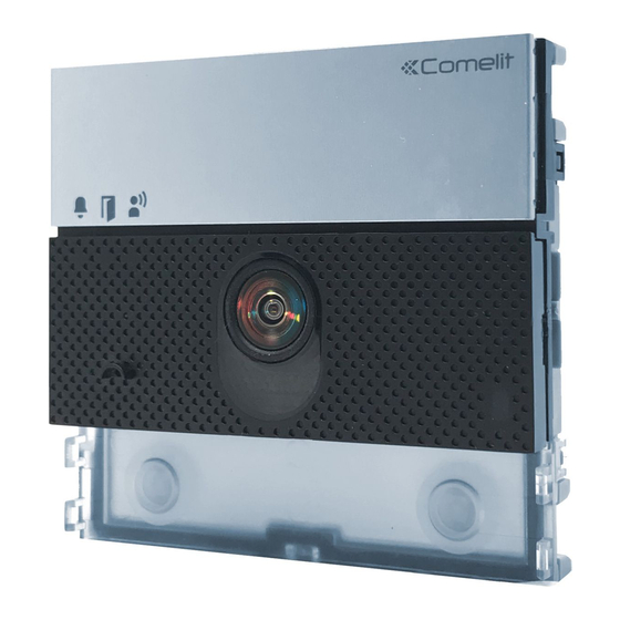
Page 4: Description
Description UT2010 Audio module for Ultra entrance panel, Simplebus2 system. For use in systems with power supply unit art. 1210 / 1210A. Easy to install and simple to configure, thanks to the smart programming of call buttons. Twilight sensor for automatic nameplate backlighting switch-off during daylight hours. Omnidirectional digital microphone and double loudspeaker for high-fidelity audio. - Page 5 3. 4. 5. 14. 15. 1. Indicator LEDs 13. Terminal block for connection: call sent (green) / system busy (red) RTE programmable RTE (local lock-release input) or DO input (door open indication) lock-release enabled GND SE- RTE and electric door lock input reference negative call in progress SE+ electric door lock connection...
-
Page 6: Technical Specifications
Technical specifications art. UT2010 GENERAL DATA Type Modular Product height (mm) Product width (mm) Product depth (mm) Black RAL9005, Transparent Aluminium (art. UT2010), black (art. UT2010B), white Product colour (art. UT2010W) Product weight (g) Coating material type Polycarbonate, Aluminium alloy Flush mounting Yes, with specific accessory Surface mounting Yes, with specific accessory COMPATIBLE SYSTEMS... -
Page 7: Installation
Installation The entrance panel is available in flush-mounted or surface-mounted variants: Flush-mounted installation composition table A = Flush-mounted box B = Rain shield C = Flush-mounted module holder with finishing frame 3110/1 3110/1A 3110/2 3110/2A 3110/3 3110/3A 3110/4 3110/4A UT9181 UT9181B UT9182 UT9184H... -
Page 8: Flush-Mounted Installation
Flush-mounted installation Optional Optional BLACK... -
Page 9: Removing Nameplates (2A) / Module (2B)
CLACK! CLACK! CLACK! CLACK! CLACK! CLACK! The button has a nameplate which can be written on (A); alternatively, an adhesive label can be applied (B). The total thickness of the nameplate + adhesive label MAX 0,2 mm must not exceed 0.2 mm. You can visit the website pro.comelitgroup.com to download the PDF to print the entrance panel name cards, using the MAX 0,2 mm... -
Page 10: Installation With Side-By-Side Boxes
Installation with side-by-side boxes Before installing the boxes in the wall, fit the spacers. -
Page 11: Wall-Mounted Installation
Wall-mounted installation Optional Optional BLACK... -
Page 12: Removing Nameplates (2A) / Module (2B)
CLACK! CLACK! CLACK! CLACK! CLACK! CLACK! The button has a nameplate which can be written on (A); alternatively, an adhesive label can be applied (B). The total thickness of the nameplate + adhesive label MAX 0,2 mm must not exceed 0.2 mm. You can visit the website pro.comelitgroup.com to download the PDF to print the entrance panel name cards, using the MAX 0,2 mm... -
Page 13: Installation With Side-By-Side Boxes
Installation with side-by-side boxes... -
Page 14: Connections
Connections Standard connection 1210A 1210 12 VAC/VDC 18 Ω MAX R GND NO NC UT2010 Max 20 m. Local door-opener button. Connection with separate power supply 1210A 1595 1210 120-230 V 12 VAC/VDC 12 VAC/VDC 18 Ω MAX 18 Ω MAX R GND NO NC UT2010... -
Page 15: Module Connection
Module connection For systems with art. UT2010 and power supply unit art. 1210/1210A, the maximum power available for the outdoor entrance panel modules is 3.3 W. Calculate the total power consumption of the modules in your system configuration using the Consumption table. -
Page 16: Connection Of Button Modules Art. Ut9200
Connection of button modules art. UT9200 1210A 1210 12 VAC/VDC 18 Ω MAX R GND NO NC BLACK UT2010 UT9200 MAX 8 Max 20 m. Local door-opener button. Max 8 modules (Max 30 modules with additional power supply). Connection of Touchscreen module art. UT9270 Variant with separate power supply Maximum 8O utenti... -
Page 17: Connecting Digital Call Module Art. Ut9260M
Connecting digital call module art. UT9260M 1210A 1210 12 VAC/VDC 18 Ω MAX R GND NO NC UT2010 UT9260M Max 20 m. Local door-opener button. -
Page 18: Programming
Programming For correct programming, follow the instructions below in order Configure button type Address button modules III. Program user codes Configuring the button type to maintain during normal operation (single/dual) DIP 6: configuring button type: Single button (DIP6 ON). default Dual button (DIP6 OFF, default). -
Page 19: Programming Consecutive Smart User Codes
Programming consecutive smart user codes default DIP 6: configuring button type: Single button (DIP6 ON). Dual button (DIP6 OFF, default). BEFORE you proceed: Set the user code of the apartment S1 S2 ALL DIP-switches to OFF, including you wish to call (for example: 1) DIP 6. -
Page 20: Programming Specific User Codes
Programming specific user codes default DIP 6: configuring button type: Single button (DIP6 ON). Dual button (DIP6 OFF, default). BEFORE you proceed: Set the user code of the apartment S1 S2 ALL DIP-switches to OFF, including you wish to call (for example: 25) DIP 6. -
Page 21: Special Programming Via Dip Switch
Special programming via DIP Switch S1 S2 Make a note of the DIP-switch settings BEFORE you proceed: ALL DIP-switches to OFF, including 1. Set the dip switches DIP 6. in accordance with the function you wish to program (see Special programming table). -
Page 22: Special Programming Table
Special programming table CODE DIP SWITCHES ON FUNCTIONS Audio-visual messages 1,7,8 Czech 1,2,7,8 Hebrew 3,7,8 Polish 1,3,7,8 Catalan 2,3,7,8 Galician 1,2,3,7,8 Basque 2,3,4,7,8 Danish 1,2,3,4,7,8 Norwegian 1,2,5,7,8 Swedish 1,2,3,5,7,8 Italian 4,5,7,8 French 1,4,5,7,8 Spanish 2,4,5,7,8 Dutch 1,2,4,5,7,8 Greek 3,4,5,7,8 English 1,3,4,5,7,8 German 2,3,4,5,7,8... - Page 23 1,2,5,6,7,8 Reset wait time (after hang-up or after lock-release): 10 sec (default) 3,5,6,7,8 Reset wait time (after hang-up or after lock-release): 1 sec 5,7,8 Enables “Reset wait time" on lock-release command (default) Disables “awaiting reset time" on lock-release command (awaiting response time or talk time will be 1,5,7,8 activated) 1,4,5,6,7,8...
-
Page 24: Twilight Sensor
Twilight sensor Button backlighting management The twilight sensor is in AUTO mode by default: the button LEDs light up at night and switch off during the day. To change the setting to ON (LEDs always on) or OFF Take note of the DIP-switch (LEDs always off), proceed settings as follows:... -
Page 25: Checking Twilight Sensor Operation
S1 S2 Reset the configuration of the DIP-switches Checking twilight sensor operation S1 S2 S1 S2 5 sec If it is daytime and you want to check AUTO mode operation for the twilight sensor, you can proceed as follows: 1. Enter programming mode 2. -
Page 26: Adjusting The Brightness Of The Button Leds
Adjusting the brightness of the button LEDs S1 S2 Take note of the DIP-switch settings BEFORE you proceed: 1. Enable Set ALL DIP-switches to OFF, brightness control including DIP 6. 2. Set the desired function (code 161) and press the confirm cod. -
Page 27: Light-Me Function
Light-me function Thanks to this function, button backlighting is only enabled on the user’s request, by pressing the LIGHT-ME button on the audio module; this saves energy and reduces light pollution. Backlighting management for this button depends on the twilight sensor setting. It is in AUTO mode by default: the LEDs light up at night and switch off during the day. -
Page 28: Replacing The Audio Module With Programming Restore Backup
Replacing the audio module with programming restore backup If the audio module is replaced, the following instructions must be observed. The procedure should be completed within one hour of removal of the old module. Make a note of the DIP-switch settings Wait for 90 seconds Enter programming mode by moving S2 DIP-switch upwards... -
Page 29: Configuring Via Pc
Configuring via PC All device configurations can be implemented via PC and ViP Manager configuration software, which is available to download free of charge from the website pro.comelitgroup.com (See programming manual) For example: • programming the user codes associated with the buttons •... -
Page 30: System Functions
System functions 6751W 2719W 2738W/A 1210A 1210 UT2010 6751W 2719W 2738W/A 1210A 1210 UT2010... -
Page 31: Operating Distances
Operating distances A MAX B MAX C MAX E MAX Comelit art. 4577/4579 1 mm² 260 m 130 m 130 m (Ø 1.2 mm AWG 17) (850 feet) (425 feet) (425 feet) UTP5 cat. 5 0.2 mm² 80 m 40 m 40 m (Ø... -
Page 32: Wiring Diagrams
Wiring diagrams 2738W/A 6751W 2719W 2738W/A 1210A 1210 230V 12 VAC/VDC 18 Ω MAX R GND NO NC UT2010 UT9200 (MAX 8) Max 20 m. Local door-opener button. For external unit configurations (model, number and type of modules) other than those indicated in the diagrams, please refer to the Outdoor entrance panel module consumption table... -
Page 33: System Performance And Layouts
1404 1404 1 2 3 4 6 7 1 2 3 4 6 7 1 2 3 4 6 7 1 2 3 4 6 7 1 2 3 4 1 2 3 4 1210A 1210 1210A 1210 230V 230V 1210A 1210 12 VAC/VDC... -
Page 34: Table Of User Codes
Table of user codes Code DIP-switch 1,4,6 1,5,7 1,4,5,6,7 1,6,8 1,4,7,8 2,4,6 2,5,7 2,4,5,6,7 2,6,8 2,4,7,8 1,2,4,6 1,2,5,7 1,2,4,5,6,7 1,2,6,8 1,2,4,7,8 3,4,6 3,5,7 3,4,5,6,7 3,6,8 3,4,7,8 1,3,4,6 1,3,5,7 1,3,4,5,6,7 1,3,6,8 1,3,4,7,8 2,3,4,6 2,3,5,7 2,3,4,5,6,7 2,3,6,8 2,3,4,7,8 1,2,3 1,2,3,4,6 1,2,3,5,7 1,2,3,4,5,6,7 1,2,3,6,8 1,2,3,4,7,8 4,5,7... - Page 35 C E R T I F I E D M A N A G E M E N T S Y S T E M S w w w . c o m e l i t g r o u p . c o m Via Don Arrigoni, 5 - 24020 Rovetta (BG) - Italy...
Need help?
Do you have a question about the Ultra Simplebus2 and is the answer not in the manual?
Questions and answers