Table of Contents
Advertisement
Quick Links
Introduction
The
STM32H573I-DK
Discovery kit is a complete demonstration and development platform for the
microcontroller, featuring an Arm
Flash memory and 640 Kbytes of SRAM, as well as smart peripheral resources.
The
STM32H573IIK3Q
microcontroller features four I
12 USARTs and one LPUART, two CAN FD, two 12-bit ADCs and two 12-bit DACs, two SAIs, one Octo‑SPI interfaces with
OTFDEC crypto and support for serial PSRAM/NOR/NAND/HyperRAM
interfaces, one USB 2.0 full-speed host and device, one USB Type-C
interface with DMA controller, one 8-bit to 14-bit camera interface, TFT LCD controller interface, JTAG, SWD and Embedded
™
Trace Microcell
(ETM) for debugging support.
The
STM32H573I-DK
Discovery kit offers everything required for users to get started quickly and develop applications easily.
The hardware features on the board help to evaluate the following peripherals: USB Type-C
10‑Mbit / 100‑Mbit Ethernet, microSD
microphone with PDM interface, 512-Mbit Octo‑SPI NOR flash memory, 20-pin microphone MEMS connector with PDM
interface, 1.54-inch TFT LCD with LED backlight and touch panel. The ARDUINO
STMod+ connectors allow easy connection of extension shields or daughterboards for specific applications. A fan-out
®
daughterboard and a Wi‑Fi
The integrated STLINK-V3EC provides an embedded in-circuit debugger and programmer for the STM32 MCU.
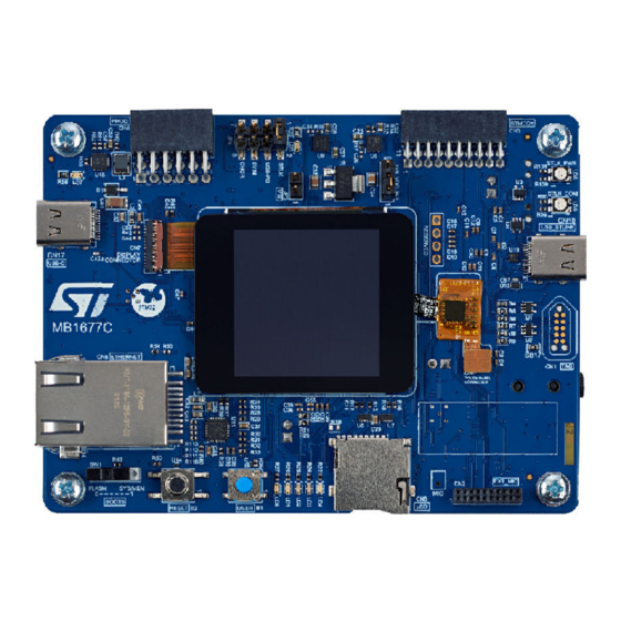
Figure 1.
STM32H573I-DK top view
Pictures are not contractual.
UM3143 - Rev 1 - July 2023
For further information contact your local STMicroelectronics sales office.
®
®
‑M33 core with Arm
Cortex
2
C, one I
™
, USART, SAI audio DAC stereo with one audio jack for input / output, ST MEMS digital
module are provided with the
Discovery kit with STM32H573II MCU
®
®
TrustZone
, frequency up to 240 MHz, 2-Mbytes of embedded
3
C, six SPIs with three multiplexed full-duplex I
™
flash memories, FMC interface, two SD/SDIO/MMC
®
/ USB power-delivery controller, one Ethernet MAC
®
Uno V3 compatible connectors, Pmod
STM32H573I-DK
Discovery kit.
Figure 2.
STM32H573I-DK bottom view
UM3143
User manual
STM32H573IIK3Q
2
S interfaces, up to
®
(Sink / Source mode),
www.st.com
™
, and
Advertisement
Table of Contents

Subscribe to Our Youtube Channel
Related Manuals for ST STM32H573I-DK


Summary of Contents for ST STM32H573I-DK
-
Page 1: Figure 1. Stm32H573I-Dk Top View
(Sink / Source mode), ™ 10‑Mbit / 100‑Mbit Ethernet, microSD , USART, SAI audio DAC stereo with one audio jack for input / output, ST MEMS digital microphone with PDM interface, 512-Mbit Octo‑SPI NOR flash memory, 20-pin microphone MEMS connector with PDM ®... -
Page 2: Features
Pmod Type-2A and Type-4A expansion – Audio MEMS daughterboard expansion • Flexible power-supply options: ST-LINK USB V , USB connector, or external sources • On-board STLINK-V3EC debugger/programmer with USB re-enumeration capability: mass storage, Virtual COM port, and debug port •... -
Page 3: Ordering Information
The meaning of the codification is explained in Table Table 2. Codification explanation STM32TTXXY-DK Description Example: STM32H573I-DK STM32TT MCU series in STM32 32-bit Arm Cortex MCUs STM32H5 series MCU product line in the series STM32H563/573 product line STM32 flash memory size: 2 Mbytes •... -
Page 4: Development Environment
STM32 flash memory for easy demonstration of the device peripherals in standalone mode. The latest versions of the demonstration source code and associated documentation can be downloaded from www.st.com. UM3143 - Rev 1 page 4/53... -
Page 5: Conventions
UM3143 Conventions Conventions Table 3 provides the conventions used for the ON and OFF settings in the present document. Table 3. ON/OFF convention Convention Definition Jumper JPx ON Jumper fitted Jumper JPx OFF Jumper not fitted Jumper JPx [1-2] Jumper fitted between Pin 1 and Pin 2 Solder bridge SBx ON SBx connections closed by 0 Ω... -
Page 6: Safety Recommendations
UM3143 Safety recommendations Safety recommendations Targeted audience This product targets users with at least basic electronics or embedded software development knowledge like engineers, technicians, or students. This board is not a toy and is not suited for use by children. Handling the board This product contains a bare printed circuit board. -
Page 7: Delivery Recommendations
UM3143 Delivery recommendations Delivery recommendations Before the first use, check the board for any damage that might have occurred during shipment, and check that all socketed components are firmly fixed in their sockets and that none is loose in the plastic bag. UM3143 - Rev 1 page 7/53... -
Page 8: Hardware Layout And Configuration
™ V3EC, push-buttons, LEDs, Octo‑SPI flash memory, LCD, microSD card, USB, Ethernet, audio codec, MEMS ™ ® digital microphones, STMod+/Pmod /ARDUINO connectors). Figure 3. STM32H573I-DK hardware block diagram ® USB Type-C USART1 USB-C STLINK-V3EC Sink and Source Trace connector TRACE... -
Page 9: Figure 4. Stm32H573I-Dk Pcb Layout: Top Side
UM3143 Hardware layout Figure 4 Figure 5 show the locations of these features on the STM32H573I-DK. Figure 4. STM32H573I-DK PCB layout: top side Pmod™ Power source VDD_MCU power connector (CN6) selection (JP4) selection (JP2) STMod+ connector (CN3) ST-LINK power USB V... -
Page 10: Mechanical Dimensions
(CN9) Audio codec IDD measurement (U25) (JP6) ® ® MEMS digital ARDUINO ARDUINO connector (CN14) connector (CN16) microphone (U20) MIPI20 TRACE connector (CN18) Mechanical dimensions Figure 6. STM32H573I-DK mechanical dimensions (top, in millimeters) 105.00 UM3143 - Rev 1 page 10/53... -
Page 11: Embedded Stlink-V3Ec
STLINK-V3EC product (for example to add new functionalities, fix bugs, and support new microcontroller families), it is recommended to keep the STLINK-V3EC firmware up to date before starting to use the STM32H573I-DK board. The latest version of this firmware is available from the www.st.com website. -
Page 12: Figure 7. Connecting An External Debug Tool To Program The On-Board Stm32
Using an external debug tool to program and debug the on-board STM32 When using the external debug connectors (CN12 or CN18), the STLINK-V3EC can be used to supply the ® STM32H573I-DK board through CN10 USB Type-C connector. Otherwise, another power supply source can be used as described on Section 9 Power supply. -
Page 13: Table 4. Stdc14 / Mipi10 Debug Connector Pinout (Cn12)
UM3143 Using an external debug tool to program and debug the on-board STM32 Table 4 describes the STDC14 / MIPI10 connector pinout (CN12). Table 4. STDC14 / MIPI10 debug connector pinout (CN12) MIPI10 STDC14 CN12 Designation Reserved Reserved T_VCC Target VCC Target SWDIO using SWD protocol or target JTMS (T_JTMS) T_SWDIO using JTAG protocol... -
Page 14: Table 5. Mipi20 Debug Connector Pinout (Cn18)
UM3143 Using an external debug tool to program and debug the on-board STM32 Table 5 describes the MIPI20 connector pinout (CN18). Table 5. MIPI20 debug connector pinout (CN18) MIPI20 pin CN18 Designation Target VCC Target SWDIO using SWD protocol or target JTMS using JTAG SWDIO/JTMS protocol Ground... -
Page 15: Power Supply
Supplying the board by the STLINK-V3EC USB Type-C connector (default setting) To power the STM32H573I-DK in this way, the USB Host (a PC) needs to be connected to the STLINK-V3EC ® USB Type-C connector of the STM32H573I-DK via a USB cable. In this case, JP4 must be fitted on pin [1-2] to select the STLK power source. -
Page 16: Table 7. External Power Source: Vin (7-12 V)
UM3143 Supplying the board by VIN (7-12 V, 800 mA max.) Figure 9. JP4 set on the VIN pin When using STLINK-V3EC for debug when powering the board with an external power supply from VIN, it is important to power the board first, before connecting the host PC to CN10, which requires the following sequence to be respected: Set the jumper between the pins 5-6 of JP4 “5VIN.”... -
Page 17: Supplying The Board By An External Usb Charger
Supplying the board by an external USB charger ® The STM32H573I-DK can also be supplied by an external charger through the STLINK-V3EC USB Type-C connector (CN10). In this case, the 5 V power source selector (JP4) must be placed on pin 7-8 (“CHGR” on the silkscreen). In this power supply mode, the debug features are not available. -
Page 18: Supplying The Board By The User Usb Type-C ® Connector
Supplying the board by the user USB Type-C connector ® The STM32H573I-DK can be supplied from the user USB Type-C connector (CN17). In this case, the 5 V power source selector (JP4) must be placed on pin 3-4 (“USB-PD” on the silkscreen). -
Page 19: Mcu Power Supply
UM3143 MCU power supply MCU power supply The STM32H573I-DK board is assembled with STM32H573IIK3Q MCU (internal SMPS version). Consequently, the MCU V logic supply is provided by the internal DC/DC converter (SMPS). CORE The hardware implementation is detailed below: Table 10. -
Page 20: Measurement Of Mcu Current Consumption
UM3143 Measurement of MCU current consumption Measurement of MCU current consumption The jumper JP6 allows the current consumption of the STM32H573IIK3Q MCU to be measured directly by removing the jumper and replacing it by an external ammeter. If there is no ammeter, the STM32H573IIK3Q MCU cannot be powered. -
Page 21: Clock Source
UM3143 Clock source Clock source Three clock sources are available on the STM32H573I-DK board, as described below: • X3: 25 MHz oscillator for the STM32H573IIK3Q HSE system clock and for the Ethernet PHY • X2: 32.768 kHz crystal for the STM32H573IIK3Q embedded RTC •... -
Page 22: Reset Sources
UM3143 Reset sources Reset sources The general reset of the STM32H573I-DK board is active low. The reset sources include: • The B2 reset button • The embedded STLINK-V3EC ® ® • The ARDUINO Uno shield board through the CN14 ARDUINO Uno V3 connector (pin 6). -
Page 23: Board Functions
TFT LCD 240 × 240 pixels and capacitive touch panel The STM32H573I-DK board includes a 1.54-inch TFT LCD with 240 × 240 pixel resolution (which is driven by the on-board display controller), white LED backlight, and capacitive touch panel. Each pixel can display 262 000 different colors. -
Page 24: Ethernet
3.3 V only. (JP2 must be ON [1-2]). 14.5 Audio The audio codec used on the STM32H573I-DK is a low-power stereo codec with a headphone amplifier, which is connected to the STM32H573IIK3Q SAI2 interface. It communicates with the STM32H573IIK3Q microcontroller ®... -
Page 25: Octo-Spi Nor Flash Memory
(STR) or double transfer rate (DTR) mode. The RESETn of the flash memory is connected to the general reset (NRST) of the STM32H573I-DK board. ‑ SPI flash memory operates at 3.3 V only (JP2 must be fitted on [1-2]). -
Page 26: Tag
The TAG supports 1.8 V or 3.3 V for target reference voltage. 14.10 JTAG/SWD/TRACE The STM32H573I-DK Discovery kit offers different ways to connect an external debugging/programming probe. Depending on the debugger tool and used cable, the STM32H573I-DK offers 10-pin or 20-pin target board connector solutions. UM3143 - Rev 1 page 26/53... -
Page 27: Mipi10 Connector (Cn12)
The MIPI10 connector supports 1.8 V or 3.3 V for target reference voltage. 14.10.2 MIPI20 connector (CN18) The STM32H573I-DK board also includes a MIPI20 connector (CN18) for debug features (SWD or JTAG) as well as ETM instruction trace. Important: Always make sure to set the JP1 jumper before connecting any debugging probe to CN18 or CN12. Indeed, before connecting an external debugger to CN18 or CN12, it is mandatory to isolate the output I/Os (SWD and UART_VCP) from STLINK-V3EC. - Page 28 UM3143 Buttons and LEDs Reference Color Name Comment Tri-color (red/orange/green) STLK PWR Tri-color (red/orange/green) STLK COM UM3143 - Rev 1 page 28/53...
-
Page 29: Board Connectors
UM3143 Board connectors Board connectors 15.1 ® USB Type-C connector (CN17) ® Figure 14. USB Type-C connector CN17 ® The related pinout for the user USB Type-C connector is listed in Table ® Table 17. USB Type-C connector CN17 pinout Connector Pin number Pin name... -
Page 30: Stmod+ Connector (Cn3)
By default, the SPI5 bus is connected to control the MB1400 Wi‑Fi module. An MB1280 fan-out daughterboard is also provided with the STM32H573I-DK Discovery kit. For more information on the MB1280 fan-out daughterboard, refer to the STMod+ fan-out daughterboard's user manual (UM2695) and to the relevant datasheets of the associated modules. -
Page 31: Pmod™ Connector (Cn6)
IO (PH4) I2C1_SDA (PB7) IO (PH5) Limitation: on the STM32H573I-DK board, SPI5 and UART7 signals are used to control a device connected to ™ STMod+ or to Pmod . Therefore, when using the STMod+ connector, the user must make sure that nothing is ™... -
Page 32: Tag Connector (Cn1)
SPI5_MISO / USART7_RX (PF8/PF6) Not connected SPI5_SCK / USART7_RTS (PF7/PF8) Not connected Limitation: On the STM32H573I-DK board, SPI5 and UART7 signals are used to control a device connected to ™ ™ STMod+ or to Pmod . Therefore, when using the Pmod connector, the user must make sure that nothing is connected on the STMod+ connector. -
Page 33: Mipi10 Connector (Cn12)
UM3143 MIPI10 connector (CN12) Table 23. Audio connector CN2 pinout Pin number Description Pin number Description Not connected PDM_SAI1_CK1_EXT (PD11) PDM_SAI1_SD2 (PE4) PDM_SAI1_SD1_EXT (PD6) PDM_SAI1_SD3 (PC3) Not connected Not connected DETECTn (PE0) Not connected MEMS_LED (PE1) Not connected Not connected Not connected Not connected Not connected... -
Page 34: Mipi20 Connector (Cn18)
Ground TRACED3 Trace Data3 15.9 TFT LCD display connector (CN7) To connect the 1.54-inch TFT LCD display, the STM32H573I-DK board includes a 0.3 mm pitch FPC connector (CN7). Figure 22. TFT LCD display connector CN7 UM3143 - Rev 1 page 34/53... -
Page 35: Touch Panel Connector (Cn4)
UM3143 Touch panel connector (CN4) The related pinout for the TFT LCD display connector is listed in Table Table 26. TFT LCD display connector pinout Connector Pin number Pin name Signal name STM32 pin Function Ground FMARK LCD_TE Tearing effect DB15 LCD_D15 PD10... -
Page 36: Ethernet Rj45 Connector (Cn8)
15.11 Ethernet RJ45 connector (CN8) The STM32H573I-DK board supports 10 Mbit/s / 100 Mbit/s Ethernet communication with its PHY and the CN8 integrated Ethernet RJ45 connector. The Ethernet PHY is connected to the MCU via the RMII interface. The 25 MHz clock for the PHY is sourced from the on-board 25 MHz oscillator X3. -
Page 37: Audio Jack Connector (Cn9)
SHIELD_1 (GND) SHIELD_2 (GND) 15.12 Audio jack connector (CN9) A 3.5 mm standard stereo audio green jack output called CN9 is available on the STM32H573I-DK board for headphones. Figure 25. Audio jack connector CN9 The related pinout for the audio jack connector is listed in Table Table 30. -
Page 38: Table 31. Arduino ® Uno V3 Compatible Connectors
® Uno V3 connector is not a power input for the STM32H573I-DK board. This simplifies the power architecture. 2. The external voltage applied to pin VIN on pin 1 of CN14 must be less than 11.5 V at 25°C ambient temperature. If a higher voltage is applied on the regulator U8, it may overheat and could be damaged. -
Page 39: Stm32H573I-Dk I/O Assignment
UM3143 STM32H573I-DK I/O assignment STM32H573I-DK I/O assignment Table 32. STM32H573I-DK I/O assignment Pin number GPIO port Signal or label Comment ARD_A2 ADC12_INP0 RMII_REF_CLK RMII_MDIO ARD_D10 TIM2_CH4, SPI2_NSS ARD_A1 ADC12_INP18 ARD_A3 ACD1_INP19 ARD_A4 ACD12_INP3 RMII_CRS_DV ARD_D9 TIM1_CH1 USART1_TX PA10 USART1_RX PA11... - Page 40 UM3143 STM32H573I-DK I/O assignment Pin number GPIO port Signal or label Comment LCD_PWR_ON LCD_NE1_CS SDIO1_D0 SDIO1_D1 PC10 SDIO1_D2 PC11 SDIO1_D3 PC12 SDIO1_CK PC13 WAKEUP PC14-OSC32_IN OSC32_IN PC15-OSC32_OUT OSC32_OUT LCD_D2 LCD_D3 SDIO1_CMD LCD_TE LCD_NOE LCD_NWE PDM_SAI1_SD1 LCD_D13 LCD_D14 PD10 LCD_D15 PD11...
- Page 41 UM3143 STM32H573I-DK I/O assignment Pin number GPIO port Signal or label Comment PE15 LCD_D12 LCD_A0_RS USER_LED3 STMOD#17 USER_LED4 STMOD#1 SPI5_NSS / USART7_RX STMOD#3 SPI5_SCK / UART7_TX STMOD#4 SPI5_MISO / UART7_RTS STMOD#2 SPI5_MOSI / UART7_CTS PF10 OCSPI1_CLK PF11 STMOD#13-ADC ADC1_INP2 PF12...
- Page 42 UM3143 STM32H573I-DK I/O assignment Pin number GPIO port Signal or label Comment STMOD#8-MOSIs SPI5_MOSI STMOD#11-INT PH10 ARD_D6 TIM5_CH1 PH11 ARD_D5 TIM5_CH2 PH12 STMOD#14-PWM TIM5_CH3 PH13 LCD_RST PH14 uSD_DETECT PH15 NRST NRST BOOT0 BOOT0 ARD_D13 SPI2_SCK ARD_D12 SPI2_MISO LCD_BL_CTRL SAI2_MCLK_A SAI2_SCK_A...
-
Page 43: Stm32H573I-Dk Product Information
B01. The second line shows the board serial number used for traceability. Parts marked as “ES” or “E” are not yet qualified and therefore not approved for use in production. ST is not responsible for any consequences resulting from such use. In no event will ST be liable for the customer using any of these engineering samples in production. -
Page 44: Board Revision History
UM3143 Board revision history 17.3 Board revision history Table 34. Board revision history Board reference Board variant and revision Board change description Board limitations MB1280 (fan-out daughterboard) 3V3-C01 Initial revision No limitation ® STMod+_SPI-C01 Initial revision No limitation MB1400 (Wi‑Fi module) MB1677 (main board) H573I-C02... -
Page 45: Federal Communications Commission (Fcc) And Ised Canada Compliance
UM3143 Federal Communications Commission (FCC) and ISED Canada Compliance Statements Federal Communications Commission (FCC) and ISED Canada Compliance Statements 18.1 FCC Compliance Statement Contains FCC ID: P53-EMW3080. Part 15.19 This device complies with Part 15 of the FCC Rules. Operation is subject to the following two conditions: (1) this device may not cause harmful interference, and (2) this device must accept any interference received, including interference that may cause undesired operation. - Page 46 UM3143 ISED Compliance Statement Déclaration de conformité Avis: Le présent appareil est conforme aux CNR d'ISDE Canada applicables aux appareils radio exempts de licence. L'exploitation est autorisée aux deux conditions suivantes : (1) l'appareil ne doit pas produire de brouillage, et (2) l'utilisateur de l'appareil doit accepter tout brouillage radioélectrique subi, même si le brouillage est susceptible d'en compromettre le fonctionnement.
-
Page 47: Revision History
UM3143 Revision history Table 35. Document revision history Date Revision Changes 27-Jul-2023 Initial release. UM3143 - Rev 1 page 47/53... -
Page 48: Table Of Contents
UM3143 Contents Contents Features................2 Ordering information . - Page 49 STM32H573I-DK product information........
- Page 50 UM3143 Contents 18.1 FCC Compliance Statement ........... . 45 18.2 ISED Compliance Statement .
-
Page 51: List Of Tables
STM32H573I-DK I/O assignment ........ -
Page 52: List Of Figures
STM32H573I-DK mechanical dimensions (top, in millimeters)........ - Page 53 ST’s terms and conditions of sale in place at the time of order acknowledgment. Purchasers are solely responsible for the choice, selection, and use of ST products and ST assumes no liability for application assistance or the design of purchasers’...
Need help?
Do you have a question about the STM32H573I-DK and is the answer not in the manual?
Questions and answers