Table of Contents
Advertisement
Quick Links
Advertisement
Table of Contents

Related Manuals for BK Precision PR65 Series


Summary of Contents for BK Precision PR65 Series
-
Page 2: Table Of Contents
Contents Compliance Information Safety IEC Measurement Category & Pollution Degree Definitions Environmental Product End-of-Life Handling Terms and Symbols Safety Notices Introduction Key Features Supplied Accessories Probe Setup Setup Specifications Safety Specifications Electrical Specifications (Not Warranted) Mechanical Specifications (same for both versions)) Environmental Specifications (same for both versions) Performance Plots Performance Verification... -
Page 3: Compliance Information
Compliance Information 1.1 EMC EC Decalration of Conformity - EMC Compliance was demonstrated to the following specifications listed in the Official Journal of the European Communities: EMC Directive 2014/30/EU. EN 61326-1:2013. Electrical equipment for measurement, control and laboratory use- EMC requirements Part 1: General requirements.Safety 1.2 Safety EC Declaration of Conformity - Low Voltage Compliance was demonstrated to the following specification as listed in the Official Journal of the European... -
Page 4: Iec Measurement Category & Pollution Degree Definitions
Compliance Information 1.3 IEC Measurement Category & Pollution Degree Definitions Measurement Category (CAT) - classification of testing and measuring circuits according to the types of mains circuits to which they are intended to be connected. Measurement Category other than II, III, or IV : circuits that are not directly connected to the mains supply. -
Page 5: Environmental
Compliance Information 1.4 Environmental Restriction of Hazardous Substances (RoHS 2) The product and its accessories conform to the Directive 2011/65/EU (RoHS 2) on the restriction of the use of certain hazardous substances in electrical and electronic equipment, inclusive of any modification and addendum to said Directive. EN ISO 63000:2018 Technical documentation for the assessment of electrical and electronic products with respect to the restriction of hazardous substances. -
Page 6: Terms And Symbols
Compliance Information 1.6 Terms and Symbols Terms A caution statement calls attention to an operating procedure, practice, or condition, which, if not followed correctly, could result in damage to or destruction of parts or the entire product. Une mise en garde attire l’attention sur une procédure, une pratique ou une condition d’utilisation qui, si elles ne sont pas suivies correctement, pourraient endommager ou détruire une partie du produit ou le produit entier. - Page 7 Compliance Information Symbols – Statements or instructions that must be consulted in CAUTION order to find out the nature of the potential hazard and any actions which must be taken. - HIGH VOLTAGE - possibility of electric shock. WARNING Earth (ground) TERMINAL - Refer to the instructions accompanying this symbol in this manual.
-
Page 8: Safety Notices
Safety Notices These test probes have been designed and tested in accordance with accepted industry and has been supplied is a safe condition. Before applying power, verify that the correct safety precautions are taken (see the following warnings). In addition, note the external markings on the instrument that are described under “Symbols”... - Page 9 Safety Notices Connect and Disconnect the Probe Properly. Connect the probe to the oscilloscope before connecting the probe inputs to the circuit under test. Disconnect the probe inputs from the circuit under test before disconnecting the probe from the oscilloscope. Connectez et déconnectez correctement la sonde.
- Page 10 Safety Notices Do Not Operate Without Covers. To avoid electrical shock, or fire hazard, do not operate these probes with cover removed. Ne pas utiliser sans couvercles. Pour éviter les chocs électriques ou les risques d’incendie, n’utilisez pas ces sondes avec le couvercle retiré.
- Page 11 Safety Notices Periodically inspect your probe and probe wires to check for any damage. Do Not Operate with Visible or Suspected Failures. If you suspect there is damage, have it inspected by B&K Precision authorized service personnel. Inspectez périodiquement votre sonde et ses fils pour vérifier qu’ils ne sont pas endommagés.
-
Page 12: Introduction
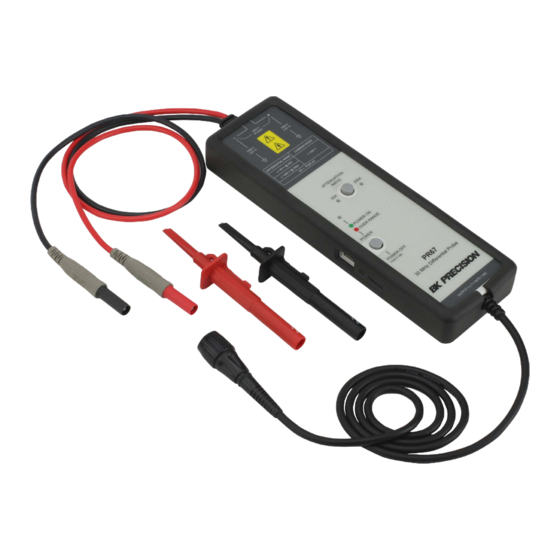
MHz of bandwidth. The probes can be powered by any oscilloscope USB port, internal batteries (4 AA batteries included with the probe), or included mains power adapter. shows some key features Figure 3.1 of the PR65 Series probe. Figure 3.1 Probe and Supplies Accessories... -
Page 13: Key Features
Introduction 3.1 Key Features Features Description Attenuation Selection Press the Attenuation selection button to switch between the two ranges. Button & LED Indicators LED indicator will light green for attenuation selected. Power Button Press to turn unit on. Press and hold for 5 seconds to turn unit off. Power and Overload LED will turn green when the unit is on. -
Page 14: Supplied Accessories
Introduction 3.2 Supplied Accessories Accessory Model No. Quantity Probe Hook, Pair CT4386 (black & red) Protective Rubber Boot, CT4470-0 Black USB Power Cord CT4473-100 (1 m)(USB-A to USB-C) Power Adapter, N.A. Plugs - USB Jack Input: 100-240 CT4471 Vac, 50/60 Hz Output: 5 Vdc, 1 A UL Listed EU Plug Converter CT4472... -
Page 15: Probe Setup
Probe Setup Before connecting the probe for your measurement, read all the warnings in this section and all of the warnings in the section “Safety Notices” Avant de connecter la sonde pour votre mesure, lisez tous les avertissements de cette section et tous les avertissements de la section “Safety Notices”... - Page 16 Probe Setup La sonde doit être mise à la terre. Avant d’effectuer les connexions aux fils d’entrée de la sonde, assurez-vous que le connecteur BNC de sortie est connecté au canal d’entrée BNC de l’oscilloscope ET que l’oscilloscope est correctement mis à la terre. Step 4.
-
Page 17: Specifications
Specifications The probe and oscilloscope should be warmed up for at least 20 minutes before any testing and the environmental conditions should not exceed the probe’s specified limits. All entries included in the following tables are characteristics unless otherwise stated. Toutes les entrées incluses dans les tableaux suivants sont des caractéristiques, sauf indication contraire. -
Page 18: Electrical Specifications (Not Warranted)
Specifications 5.2 Electrical Specifications (Not Warranted) Parameter PR65 PR67 Bandwidth (-3 dB) 30 MHz 30 MHz Gain Accuracy ± ± Attenuation Ratio 10x / 100x 20x / 200x Rise Time 14 ns 14 ns Absolute Maximum Rated Input Voltage 1000 V CAT III 1000 V CAT III (each side to ground) Maximum Differential Input... -
Page 19: Mechanical Specifications (Same For Both Versions))
Specifications 5.3 Mechanical Specifications (same for both versions)) Parameter Characteristic Input Leads Length (each) 55 cm ±3 cm BNC Cable Length 95 cm ±3 cm Dimension (L x W x H) 220 mm, 68 mm, 28 mm (with protective rubber boot) Weight 488 g (1.08 lb) (with batteries and protective rubber boot) USB Type C Cable Length... -
Page 20: Performance Plots
Performance Plots Figure 6.1 Riste Time 10x attenuation, 10%-90%... - Page 21 Performance Plots Figure 6.2 Riste Time 100x attenuation, 10%-90%...
- Page 22 Performance Plots Figure 6.3 Riste Time 20x attenuation, 10%-90%...
- Page 23 Performance Plots Figure 6.4 Riste Time 200x attenuation, 10%-90%...
- Page 24 Performance Plots Figure 6.5 Typical Voltage Derating Typical derating plog of the absolute maximum input voltage in commond mode.
-
Page 25: Performance Verification
Performance Verification 7.1 Required Equipment The follow procedures can be used to test the differential gain accuracy and rise time. Please note that these procedures do not indicate that the characteristics are warranted. They are meant to indicate the probe is functioning properly. Allow the probe to warm up at least 20 minutes. -
Page 26: Test Procedures
Performance Verification 7.2 Test Procedures 7.2.1 Setup Step 1. Turn on the oscilloscope. Step 2. Connec the probe to any channel on the oscilloscope for (warm-up). It is recommended to operate the probe using USB power during verification testing. Il est recommandé d’utiliser la sonde en utilisant l’alimentation USB pendant les tests de vérification. - Page 27 Performance Verification Figure 7.1 Gain Accuracy Set up Step 3. Connect the probe’s input leads to the generator/calibrator outputs using banana plug adapters. Step 4. Set the DMM to AC volts. Step 5. Set the probe’s attenuation range and the generator/calibrator to square wave output, frequency and RMS voltage to the values show in Table 8 7.2, for the probe being tested.
-
Page 28: Rise Time
Performance Verification 7.2.3 Rise Time Step 1. Verify that the pulse generator output is off and then connect the probe to the oscilloscope input channel. Step 2. Connect the probe inputs, through the adapters shown below, to the pulse generator output. Set the probe input leads straight and parallel for best signal response. - Page 29 Performance Verification Probe Pulse Generator Probe Output Model Range Voltage Frequency Expected (ns) Measured (ns) PR65 50 V 1 kHz 11.7 ns PR65 100x 50 V 1 kHz 11.7 ns PR67 50 V 1 kHz 11.7 ns PR67 200x 50 V 1 kHz 11.7 ns Table 7.3 Rise Time Test Equipment Settings...
-
Page 30: Cleaning
Cleaning Clean only the exterior probe body and cables. Use a soft cotton cloth light moistened with a mild solution of detergent and water. Do not allow any portion of the probe to be submerged at any time. Dry the probe thoroughly before attempting to make voltage measurements. - Page 31 China RoHS 2 Hazardous Substances Disclosure Table China RoHS 2 refers to the Ministry of Industry and Information Technology Order No. 32, effective July 1, 2015, titled Management Methods for the Restriction of the Use of Hazardous Substances in Electrical and Electronic Products. To comply with China RoHS 2, we determined this product’s Environmental Protection Use Period (EPUP) to be 25 years in accordance with the Marking for the Restricted Use of Hazardous Substances in Electronic and Electrical Products, SJT 11364.
-
Page 32: Service Information
Service Information Warranty Service: Please go to the support and service section on our website at bkprecision.com to obtain an RMA #. Return the product in the original packaging with proof of purchase to the address below. Clearly state on the RMA the performance problem and return any leads, probes, connectors and accessories that you are using with the device.
Need help?
Do you have a question about the PR65 Series and is the answer not in the manual?
Questions and answers