
Related Manuals for Gossen MetraWatt ENERGYMID EM2281


Summary of Contents for Gossen MetraWatt ENERGYMID EM2281
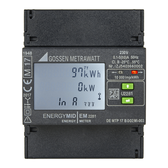
- Page 1 Operating Instructions 2/10.22 3-447-121-03 ENERGYMID MULTIFUNCTIONAL ENERGY METERS EM2281, EM2289 – DIRECT CONNECTION EM2381, EM 2387, EM2389 – TRANSFORMER CONNECTION...
-
Page 2: Table Of Contents
CONTENTS CONTENTS Safety Instructions ....................................5 Applications ......................................6 Intended Use / Use for Intended Purpose ......................6 Use for Other than Intended Purpose........................6 Liability and Guarantee............................6 Documentation....................................7 Information Concerning these Instructions ......................7 Identification of Warnings ............................7 Identifiers ................................8 Definition of Terms ..............................8 Getting Started....................................9 The Instrument....................................10 Scope of Delivery ..............................10... - Page 3 CONTENTS Display and Operation..................................30 Display ................................30 Test LEDs ................................ 32 Keys ................................32 7.3.1 UP and ENTER ............................32 7.3.2 Enable Key .............................. 33 Configuration and Operation ................................34 Display of Active and Reactive Energy, as well as Active and Reactive Power ..........35 8.1.1 Displaying Inductive Reactive Energy and Reactive Power (only with feature M2/M3) .......
- Page 4 CONTENTS Error ........................................53 Power Failure ..............................53 Fault Conditions and Troubleshooting .......................53 Maintenance .....................................54 10.1 Cleaning ................................54 10.2 Recalibration..............................54 10.3 Repairs ................................56 Removal from Service and Dismantling............................57 11.1 Disconnection from the Power Supply ......................57 11.2 Dismantling ...............................58 Transport and Storage ..................................59 Contact, Support and Service ................................60 Disposal and Environmental Protection ............................61 Certifications.....................................62...
-
Page 5: Safety Instructions
SAFETY INSTRUCTIONS SAFETY INSTRUCTIONS Read and follow these instructions carefully and completely in order to ensure safe and proper use. Keep for future reference. General Carefully and completely read and adhere to these operating instructions. The respective document can be found at http://www.gossenmetrawatt.com. Retain the document for future reference. The instrument may only be used for the measurements described in the documentation for the instrument. -
Page 6: Applications
ENERGYMID energy meters are ideally suited for use with other components included in GOSSEN METRAWATT’s Energy Control System (ECS) for the implementation of comprehensive systems for energy data collection: data from ENERGYMID energy meters can be retrieved by means of summators and data loggers, e.g. -
Page 7: Documentation
This document is protected by copyright. Content modifications, reproduction, duplication, processing or translation in any form (including excerpts) are only permissible after obtaining written permission from Gossen Metrawatt GmbH. This applies in particular to storage and processing in electronic systems. -
Page 8: Identifiers
Comment DEFINITION OF TERMS Instrument Energy meters ENERGYMID EM2281, EM2289, EM2381, EM2387 und EM2389. Feature Product feature (e.g. bus connection type, pulse output, measurement of reactive energy) – used to configure the instrument variant and is specified when the order is placed... -
Page 9: Getting Started
GETTING STARTED GETTING STARTED 1. Read and adhere to the product documentation. In particular observe all safety information in the documentation, on the tester and on the packaging. Safety Instructions 5 Applications 6 Documentation 7 2. Familiarize yourself with the instrument and its features 10. 3. -
Page 10: The Instrument
THE INSTRUMENT THE INSTRUMENT SCOPE OF DELIVERY Please check for completeness. Energy meter Condensed operating instructions (German, English) Calibration certificate (with feature P9 only) OPTIONAL ACCESSORIES U270B Door mounting kit for energy meter, 4 or 7 standard width units INSTRUMENT OVERVIEW 5.3.1 FRONT Display... -
Page 11: Side View
THE INSTRUMENT 5.3.2 SIDE VIEW Pulse Output or Bus Connections (feature-dependent) Tariff Connections Feature-Dependent: W1: Neuron ID Line: Serial Number W4: MAC Address Line: Features Manufacturer’s Seal 12 Terminal Cover (closed) Figure 7: Instrument, Side View DIMENSIONAL DRAWING Top-Hat Rail per EN 50022 or Snap-On Rail with C Profile Dimensions Each: 35 ×... -
Page 12: Tamper-Proof Sealing
THE INSTRUMENT TAMPER-PROOF SEALING The instrument is provided with various seals in order to protect it against unauthorized modifications. One manufacturer’s seal on the side: The manufacturer’s seal serves as the instrument’s calibration and guar- antee seal. ATTENTION Manufacturer’s Violation of Calibration Law Seal An instrument with a broken manufacturer’s seal may not be used for billing purposes. -
Page 13: Symbols On The Instrument And The Included Accessories
THE INSTRUMENT SYMBOLS ON THE INSTRUMENT AND THE INCLUDED ACCESSORIES Marking with stamp of the federally approved test laboratory (for verification only / with feature P9) CE and metrology mark with indication of year (M22) and registration number of the notified body for module D, coun- try-specific calibration validity period Metrological symbol for national approval in Germany (DE = Germany, M = Metrology) with indi- DE-M 22... -
Page 14: Relevant Standards, Regulations And Directives
THE INSTRUMENT RELEVANT STANDARDS, REGULATIONS AND DIRECTIVES The instrument has been manufactured and tested in accordance with the following safety regulations. ATTENTION The design of the device does not release the user from the obligation to comply with legal regulations. Violation of legal regulations. -
Page 15: Technical Data
THE INSTRUMENT TECHNICAL DATA Some of the technical data are model and feature-dependent: You selected the device type and (optional) features when you placed your order. All options are listed with corresponding identification in the following table. The features included with your instrument can be found on the label on its side (10) or in your order documents. - Page 16 THE INSTRUMENT Pollution degree: Protection category: Insulating group: Utilization category (only for meters with direct connection) UC-2 (electrical switchgear): (per EN 60947) Inputs: 300 V Nominal insulation voltage: Output: 50 V (bus/S0) with V0, V1, V2, V7, V8, V9 230 V (pulse) with V3, V4 Input ...
- Page 17 THE INSTRUMENT The energy meters are equipped with two pulse outputs or one bus output as a standard feature. Model and feature-dependent, as well as optional: S0 standard, calibrated, 1000 pls/kWh (V1) / S0 programmable, 1 … 1000 pls/kWh sec. (V2 with EM2281, EM2289) / S0 programmable, 1 …...
-
Page 18: Characteristic Values
THE INSTRUMENT 5.10 CHARACTERISTIC VALUES 5.10.1 MEASURING RANGES Reference voltage U AC: U3: 100 … 110 V L–L 230 V L–N Voltage 400 V L–L 500 V L–L Allowable deviation: -20% … +15% Direct connection: Transformer connec- tion: Starting current Direct connection: 20 mA Transformer connec-... -
Page 19: Bus Interfaces
THE INSTRUMENT Direct connection: Pulse frequency is proportional to measured energy. Transformer connection: Primary values are transmitted. Pulse frequency is proportional to primary energy and the selected CT value (current transformer ratio) is taken into consideration. The pulse outputs are electrically isolated from the measuring circuit by means of an optocoupler. Electrical Values With direct connection: 1000 pls/kWh (adjustable with V2/V4) -
Page 20: Block Diagram For Safety Specification
THE INSTRUMENT 5.10.6 BLOCK DIAGRAM FOR SAFETY SPECIFICATION Uniform internal interface 5.11 OBIS FIGURES Tab. 3: OBIS Figures (object identification system) per EN 62056-61 OBIS OBIS Measured Quantity Measured Quantity Figure Figure Total 1.8.0 Total: 2.8.0 Tariff 1: 1.8.1 Tariff 1: 2.8.1 Tariff 2: 1.8.2... -
Page 21: Initial Startup
INITIAL STARTUP INITIAL STARTUP Initial instrument startup includes installation at the place of use as well as connection to your equipment: "Unpacking" 21 "Installation" 21 "Connection to Your Equipment (interfaces)" 28 Note This document only describes technical startup of the instrument. Inform yourself about further measures that may have to be taken into ac- count during initial startup, for example, documentation (installation verifi- cations, meter numbers, meter readings etc.) or other administrative... -
Page 22: Mounting
INITIAL STARTUP 6.2.1 MOUNTING The instrument may only be mounted inside an external housing, e.g. switch cabinet or meter cabinet. The housing must provide at least IP 51 protection and must be located indoors. Only in this case is protection against dust and water ingress guaranteed in accordance with the EN 50470-1. -
Page 23: Connection
INITIAL STARTUP Rail Mounting Required tool: small slotted screwdriver The installation location is an enclosure with IP 51 protection located indoors. A top-hat rail in accordance with EN 50022 or a snap-on rail with C-profile (dimensions: 35 × 15 mm or 35 × 7.5 mm) is available at the installation site. - Page 24 INITIAL STARTUP a. For detailed information, refer to the interface description for your instrument which can be found at: https://www.gmc-instruments.de/en/services/download-center/ Terminal Assignments All connection elements are laid out as self-locking screw terminals (slotted screws, 16 mm² cross-section), except for the TCP/IP interface which is equipped with an RJ-45 connector.
- Page 25 INITIAL STARTUP EM2381 – Transformer Connection EM2387 – Transformer Connection 2-Wire AC System, Any Load 3-Wire AC System, Any Load 1 2 3 EM2389 – Transformer Connection 4-Wire AC System, Any Load 1 2 3 Wiring Diagrams – Pulse Output Feature V1 / V2 / V7 / V8 / V9: External Voltage Source I = max.
- Page 26 INITIAL STARTUP Tariff Connections For the hardware-controlled tariff connections, tariff inputs Ta and Tb are each connected with reference to Tn. Tariff Inputs Tariff 1 Level 0: < 12 V Level 1: 45 … 265 V Tariff 2 Tariff 3 Tariff 4 Procedure Required tool: small slotted screwdriver...
- Page 27 INITIAL STARTUP Note The installation technician is responsible for: Coordination of the rated values and the characteristic values of the overcurrent protection devices on the supply side, including maximum current rating values. The rated utilization category of the metering equipment in case of ...
-
Page 28: Display Of Connection Errors And Troubleshooting
Observe and follow the associated product documentation for connection to other components. For example, instructions for interaction with other components from the product range of Gossen Metrawatt GmbH – e.g. SMARTCONTROL and SU1604 summators or EMC 5.x energy management software – can be found in the respective product documentation. -
Page 29: M-Bus Installation (Feature W2)
INITIAL STARTUP 6.3.2 M-BUS INSTALLATION (FEATURE W2) The M-Bus interface has been electrically connected during installation (21). The EnergyMID software tool provides as- sistance when starting up the interface. All information and files required to this end can be found on the download page for your instrument at: https://www.gmc-instruments.de/en/services/download-center/ 6.3.3... -
Page 30: Display And Operation
DISPLAY AND OPERATION DISPLAY AND OPERATION DISPLAY Measured quantities (e.g. active energy) and information (e.g. active tariff) appear at the instrument’s display. Depending on the type of multifunctional variant, the instrument is capable of acquiring reactive power and indicating up to 33 additional measured quantities directly at the display. - Page 31 DISPLAY AND OPERATION Background Illumination The display is illuminated. Background illumination is activated whenever a key is pressed. It goes out if no keys are pressed for a duration of 2 minutes. Colors indicate various display menus: Table 4: Meanings of Background Illumination Colors Color Meaning Retrieval menus for viewing values (...
-
Page 32: Test Leds
DISPLAY AND OPERATION Standard Display and Calibration Display Resolution Table 6: Standard Display and Calibration Display Calibration Meter / Feature CT × VT min. CT × VT max. Standard display Unit display * — — 123456.78 23456.789 Direct Meter EM2281, EM2289 12345.678 2345.6789 12345.678... -
Page 33: Enable Key
DISPLAY AND OPERATION 7.3.2 ENABLE KEY The enable key makes it possible to enable or disable parameter changes. It’s located behind the top terminal cover between terminals 21 and 22. See "Instrument Overview" 10. The enable key can be activated with a pointed object (e.g. an ESD safe screwdriver). DANGER Slipping and touching the screw terminals. -
Page 34: Configuration And Operation
CONFIGURATION AND OPERATION CONFIGURATION AND OPERATION The standard display (active energy and active power import) appears by default: 12345 . Accuracy of active energy EP … EP , EP (kWh): ± 1% 67 8 4567 Accuracy of active power P (kW): 1% ±... -
Page 35: Display Of Active And Reactive Energy, As Well As Active And Reactive Power
CONFIGURATION AND OPERATION Which values do you want to display or which parameters do you want to adjust? "Transformation Ratio (EM2381, EM2387 and EM2389 only)" 47 "Switching Amongst Tariffs" 36 "Power Displays (feature M1/M3 only)" 40 "Mains Monitor (only with feature M1/M3)" 42 ... -
Page 36: Displaying Total Active Energy Import (All)
CONFIGURATION AND OPERATION 8.1.4 DISPLAYING TOTAL ACTIVE ENERGY IMPORT (ALL) AND REACTIVE ENERGY IMPORT (ONLY WITH FEATURE M2/ T1T3 2345 67 8 T2T4 1 2345 For all tariffs. kVArh Accuracy of active energy EP … EP , EP (kWh): ± 1% Accuracy of reactive energy EQ …... - Page 37 CONFIGURATION AND OPERATION 12345 67 8 The standard display is the starting point. 4567 Tariff 1 (T1) – Import 1. Briefly press the ENTER key. Active energy import is displayed for tariff 1. 12345 67 8 In the case of feature M2/M3, reactive energy import is also displayed for tariff 1. 1 2345 kVArh ...
-
Page 38: Displaying Total Active Energy And Total Reactive Energy Import (Only With Feature M2, M3)
CONFIGURATION AND OPERATION 8.2.2 DISPLAYING TOTAL ACTIVE ENERGY AND TOTAL REACTIVE ENERGY IMPORT (ONLY WITH FEATURE M2, M3) The various tariffs are shown in successive displays. As a result, you may have to cycle through multiple displays. Total active energy import is displayed for each tariff, and total reactive energy import is also displayed for instruments with feature M2 or M3. - Page 39 CONFIGURATION AND OPERATION Tariff 3 (T3) – Export 1. Briefly press the ENTER key twice in succession at short intervals. 2. Press the UP key 6 times in succession at short intervals. 12345 67 8 Active energy export is displayed for tariff 3. 1 2345 kVArh In the case of feature M2/M3, reactive energy export is also displayed for tariff 3.
-
Page 40: Power Displays (Feature M1/M3 Only)
CONFIGURATION AND OPERATION POWER DISPLAYS (FEATURE M1/M3 ONLY) Available displays differ according to the number of conductors. 8.3.1 4-WIRE DISPLAYS The various values are shown in successive displays. As a result, you may have to cycle through multiple displays. The linear path is described on the left. In contrast, the absolute number of keys required from the starting point to the de- sired display is shown on the right in the various sections. -
Page 41: 3-Wire Displays
CONFIGURATION AND OPERATION 8.3.2 3-WIRE DISPLAYS The various values are shown in successive displays. As a result, you may have to cycle through multiple displays. The linear path is described on the left. In contrast, the absolute number of keys required from the starting point to the desired display is shown on the right in the various sections. -
Page 42: Mains Monitor (Only With Feature M1/M3)
CONFIGURATION AND OPERATION MAINS MONITOR (ONLY WITH FEATURE M1/M3) 8.4.1 4-WIRE DISPLAYS The various values are shown in successive displays. As a result, you may have to cycle through multiple displays. The linear path is described on the left. In contrast, the absolute number of keys required from the starting point to the desired display is shown on the right in the various sections. -
Page 43: 3-Wire Displays
CONFIGURATION AND OPERATION 8.4.2 3-WIRE DISPLAYS The various values are shown in successive displays. As a result, you may have to cycle through multiple displays. The linear path is described on the left. In contrast, the absolute number of keys required from the starting point to the desired display is shown on the right in the various sections. -
Page 44: S0 Pulse Output (Only With Feature W0)
CONFIGURATION AND OPERATION S0 PULSE OUTPUT (ONLY WITH FEATURE W0) The linear path is described on the left. In contrast, the absolute number of keys required from the starting point to the desired display is shown on the right in the various sections. 12345 . -
Page 45: Displaying Pulse Duration
CONFIGURATION AND OPERATION 8.5.3 DISPLAYING PULSE DURATION 1000 Pulse duration is the duration of the pulse for the ON state or HIGH value. Standard: 30 ms (adjustable and possibly different with feature V2, V4) Procedure 1. Press and hold the ENTER key. 2. -
Page 46: Selecting Pulse Sources (Only With Feature V2, V4)
CONFIGURATION AND OPERATION 8.5.6 SELECTING PULSE SOURCES (ONLY WITH FEATURE V2, V4) 4 pulse sources for pulse outputs S01 and S02: 50 srC1 – Active energy import or export – kWh – kVAr – kVAr – Reactive energy import or export C l o s e d 0 p e n 2 states: The S0 switch is either... -
Page 47: Transformation Ratio (Em2381, Em2387 And Em2389 Only)
CONFIGURATION AND OPERATION TRANSFORMATION RATIO (EM2381, EM2387 AND EM2389 ONLY) In the case of meters with transformer connection, the transformation ratios of the current transformer (CT) and the voltage transformer (VT) can be viewed. The linear path is described on the left. In contrast, the absolute number of keys required from the starting point to the desired display is shown on the right in the various sections. -
Page 48: Setting The Voltage Transformation Ratio (Vt) (Only With Feature Q1)
CONFIGURATION AND OPERATION 8.6.4 SETTING THE VOLTAGE TRANSFORMATION RATIO (VT) (ONLY 1000 WITH FEATURE Q1) Adjustable: CT × VT ≤ 100,000 Procedure 1. Press and hold the ENTER key. 2. Briefly press the UP key 4 times in succession at short intervals. ... -
Page 49: Bus Connections (Features W1, W2,W4, W7)
CONFIGURATION AND OPERATION BUS CONNECTIONS (FEATURES W1, W2,W4, W7) There are separate menus and setting options for all bus connections. Their descriptions are comprehensive and are made available in separate documents, i.e. the interface descriptions: LON-Bus (W1, document number: 3-349-908-01), M-Bus (W2, document number: 3-349-909-01), Modbus RTU (W7, document number: 3-349-910-01) and TCP/IP including BAC- net, Modbus TCP and HTTP (W4, document number: 3-349-937-01). -
Page 50: Meter Reading Profile Z2
CONFIGURATION AND OPERATION Displaying and Setting Period Duration (only with feature Z1 in combination with bus connection W1 / W2 / W4 / W7) Period duration is the time interval at which values are stored (also called the integrating period). The linear path is described on the left. -
Page 51: Firmware Version
CONFIGURATION AND OPERATION FIRMWARE VERSION 12345 . 67 8 The standard display is the starting point. 4567 Displaying the Firmware Version 1. Press and hold the ENTER key. The firmware version is displayed with a red background. version "Display Test"... -
Page 52: Calibration Display
CONFIGURATION AND OPERATION 8.11 CALIBRATION DISPLAY The calibration display includes an additional decimal place. Resolution is model and feature-dependent. See "Standard Display and Calibration Display" 32. Example: normally 100,010.00 kWh and with calibration display 100,010.005 kWh. The linear path is described on the left. In contrast, the absolute number of keys required from the starting point to the desired display is shown on the right in the various sections. -
Page 53: Error
ERROR ERROR POWER FAILURE Meter parameters and meter readings are retained in internal memory (EEPROM) in the event of power failure. FAULT CONDITIONS AND TROUBLESHOOTING The instrument is equipped with an error display: if an error occurs, the display alternates between the respective error code and active energy or instantaneous power. -
Page 54: Maintenance
MAINTENANCE 10 MAINTENANCE The instrument is maintenance-free. 10.1 CLEANING Keep outside surfaces clean. Clean the instrument with a dry cloth. DANGER Life endangering due to electric shock! Life endangering due to electric arcs! Touching voltage conducting components is life endangering. Maintenance may only be carried out by trained personnel who are ... - Page 55 MAINTENANCE ATTENTION Tamper-Proof Sealing Violation of calibration law. Seals may only be broken by authorized, qualified personnel. A calibration display can be activated for testing or calibration purposes, at which energy values are displayed with in- creased resolution "Calibration Display" 52. In the case of direct meters, testing is only possible with sources which supply currents superimposed on voltages.
-
Page 56: Repairs
10.3 REPAIRS If your instrument requires repair, please contact our service department "Contact, Support and Service" 60. The instruments are guaranteed for a period of 3 years after shipment. The manufacturer’s guarantee covers materials and workmanship. Damage resulting from use for any other than the intended purpose or operating errors, as well as any and all consequential damage, are excluded. -
Page 57: Removal From Service And Dismantling
REMOVAL FROM SERVICE AND DISMANTLING 11 REMOVAL FROM SERVICE AND DISMANTLING The instrument cannot be switched off and must instead be disconnected from the power supply. It may only be dismantled after it has been disconnected from the power supply. DANGER Danger of Injury Removal from service and dismantling involve risks which may not be recognized as... -
Page 58: Dismantling
REMOVAL FROM SERVICE AND DISMANTLING Disconnecting the instrument from the power supply 1. Remove the seals. 2. Open both terminal covers by flipping them up or down respectively. 3. Remove all connecting cables or leads. Loosen one screw terminal. ... -
Page 59: Transport And Storage
TRANSPORT AND STORAGE 12 TRANSPORT AND STORAGE If the instrument is (temporarily) removed from service, it can be stored. Please observe the notes in this section in this regard. The same applies if the instrument is transported, e.g. to a storage location or another place of use. ATTENTION Improper Transport Damage to the product and measuring error... -
Page 60: Contact, Support And Service
13 CONTACT, SUPPORT AND SERVICE Gossen Metrawatt GmbH can be reached directly and simply – we have a single number for everything! Whether you require support or training, or have an individual inquiry, we can answer all of your questions here: Monday to Thursday: 8 a.m. -
Page 61: Disposal And Environmental Protection
Old devices, electrical or electronic accessories and waste batteries (including rechargeable batteries) used in Germany can be returned free of charge to Gossen Metrawatt GmbH or the service provider responsible for their disposal in compliance with applicable regulations, in particular laws concerning packaging and hazardous goods. Further information regarding returns can be found on our website. -
Page 62: Certifications
CERTIFICATIONS 15 CERTIFICATIONS 15.1 CE DECLARATION The instrument fulfills all requirements of applicable EU directives and national regulations. We confirm this with the CE mark. This can be found on the Internet at: https://www.gmc-instruments.de/en/services/download-center/ 15.2 CALIBRATION CERTIFICATE (WITH FEATURE P9 ONLY) A calibration certificate is included with the instrument. - Page 63 APPENDIX APPENDIX Abbreviations and their Meanings: Abbreviation Meaning Current transformation ratio CT VT Product of CT times VT … EP , EP Active energy per tariff and total (across all phases) … EQ , EQ Reactive energy per tariff and total (across all phases) Frequency Current per phase (TRMS value) Neutral conductor current (calculated)
- Page 64 APPENDIX Abbreviation Meaning W4 (feature) TCP/IP (BACnet, Modbus TCP, HTTP) W7 (feature) MODBUS RTU Z0 (feature) Without meter reading profile Z1 (feature) Meter reading profile (only possible with bus connection) Z2 (feature) Certified meter reading profile per PTB-A 50.7 (only in combination with W4, not possible in combination with U3) ENERGYMID 64 | 64...
- Page 65 PLEASE CONTACT: © Gossen Metrawatt GmbH Gossen Metrawatt GmbH Prepared in Germany • Subject to change without notice / errors excepted Südwestpark 15 • A PDF version is available on the Internet 90449 Nürnberg Germany All trademarks, registered trademarks, logos, product names, and +49 911 8602-0 company names are the property of their respective owners.
Need help?
Do you have a question about the ENERGYMID EM2281 and is the answer not in the manual?
Questions and answers