
Subscribe to Our Youtube Channel
Related Manuals for Gossen MetraWatt ENERGYSENS


Summary of Contents for Gossen MetraWatt ENERGYSENS
- Page 1 Operating Instructions ENERGYSENS Power Measurement for Energy Data Management 3-349-974-03 1/12.17...
-
Page 2: Table Of Contents
TABLE OF CONTENTS Outline................................... 4 Installation ................................5 Software and Communication .......................... 10 System Configuration ........................... 13 3.1.1 Installation of the ENERGYSENS Service Tool ..................13 3.1.2 Program Start ............................13 3.1.3 General configurations and communication with the base ..............14 3.1.3.1 Language Selection ........................ - Page 3 ENERGYSENS Glossary ................................30 Technical data ..............................32 Safety instructions ............................. 33 GMC-I Messtechnik GmbH...
-
Page 4: Outline
Outline ENERGYSENS serves as detailed power measurement of single loads in 50 / 60 Hz low voltage systems. The data of such power measurement may then be used to carry out measures to e.g. improve the energy efficiency as part of an Energy Management System. -
Page 5: Installation
An inappropriate execution of installation and startup may lead to damages and/or endanger people. ENERGYSENS is only designed for usage in single and tri- phase low voltage systems with a nominal voltage of 230 / 400 V AC at 50 resp. 60 Hz. - Page 6 ENERGYSENS Power supply via terminals (voltage entries) on bottom side. Power supply For fastening, slide the connection lead into the respective terminal. To disengage use the release key. Only L1 and N are connected in single phase systems. In tri-phase systems all phases and N are connected.
- Page 7 ENERGYSENS Detached power supply line Detach possibly existing power supply lines prior to fastening the sensors. Before working on these lines, ensure that they are disconnected from the mains. Power supply line in metering points The power supply lines are lead through the openings of the metering points and are re-connected.
- Page 8 ENERGYSENS Upper part Wide side Bottom part Narrow side The plugs for the flat ribbon cable are assembled with upper and bottom part. Note that the plugs are not symmetrical. Use appropriate pliers to squeeze the plugs onto the cable.
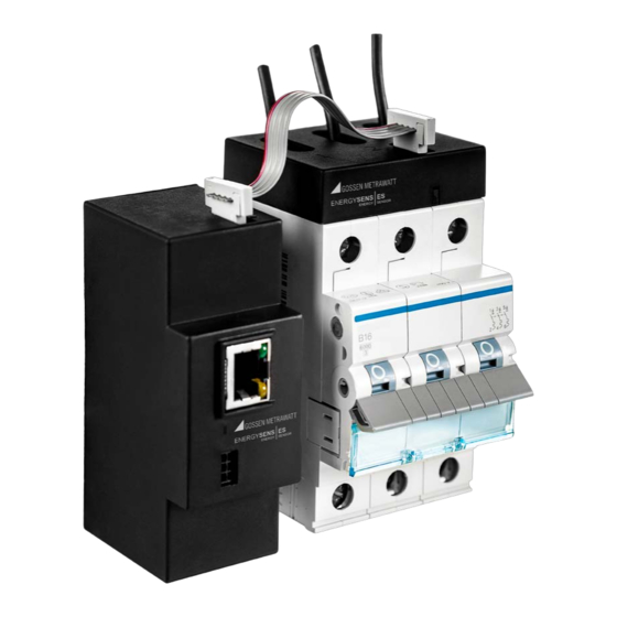
- Page 9 ENERGYSENS The base and all sensors are connected with a flat ribbon cable. As shown in the picture, the plugs are put in the Sensorbus interfaces of the base and of the voltage sensors: • The connectors are squeezed onto the cable at appropriate intervals.
-
Page 10: Software And Communication
(Flachbandkabel) Software ENERGYSENS has an internal interface via which the base communicates with the sensors. Communication to the outside takes place via the connections of the base. ENERGYSENS has a Modbus interface as external interface. Both Modbus TCP (via Ethernet) and the Modbus RTU (via RS485) protocols are supported. - Page 11 ENERGYSENS The picture shows the communication interfaces of the base. Ethernet interface A (+) RS485 interface B (-) The Ethernet interface must be connected with an Ethernet cable CAT5 or better with a 100Mbit switch. The RS485 interface is connected via the terminals. The picture shows the assignment of the signals to the base.
- Page 12 ENERGYSENS The termination of the RS485 interface in the device corresponds with this wiring: A (+) B (-) GMC-I Messtechnik GmbH...
-
Page 13: System Configuration
• Definition of the logic devices and setting of the adjustable registers 3.1.1 Installation of the ENERGYSENS Service Tool The ENERGYSENS Service Tool must only be copied to a directory on the PC. The user must have write permission in the directory. 3.1.2 Program Start To start, run the executable „ControlFramework.exe“... -
Page 14: General Configurations And Communication With The Base
In the delivery state, each base has the IP address 192.168.127.20. If, after delivery, the base is to be addressed via TCP / IP, a subnet must be established in which this address can be addressed by the ENERGYSENS Service Tool. -
Page 15: Display Of Sensors
ENERGYSENS 3.1.3.7 Display of sensors The current status of the sensors can be read with the button "Refresh list”. If the "Auto" checkbox is activated, it is updated every 3 seconds. With the "Restart Identification” button, the configuration is reset and the connected sensors are identified again. -
Page 16: Subnet Mask
• The PC must have an own IP address in the same subnet as the desired IP address of ENERGYSENS. • For the MAC address of the ENERGYSENS base (this is located on the part number sticker on the back), a static entry must be generated in the ARP table of the PC. -
Page 17: Standard Gateway
ENERGYSENS 3.1.4.2 Standard Gateway This parameter is only used for communication via TCP/IP. The parameter specifies the TCP / IP address of the default gateway in the subnet where the base is installed. Ser. Delay: The central unit answers the "Read Register" commands on the Modbus RTU interface with an adjustable delay. -
Page 18: Assigning The Sensors
ENERGYSENS 3.1.6 Assigning the Sensors A list of connected sensors is read out from the base by hitting the button „Connect“ or „Restart Identification“. Each sensor has a unique serial number. When assigning the sensors, an individual ID is assigned to the individual sensors. The ID corresponds to a sensor location within the system and is later used to read out the registers of the respective sensor. -
Page 19: Reading The Settings Of The Sensors
ENERGYSENS In this window, the corresponding voltage phase for each metering point is set up. By hitting OK, the regulated values for each sensor are saved for the respective sensor. When using adjustable Modbus registers, the phase assignment has to be carried out when creating the register configuration. -
Page 20: Read Out Of Sensor Measurements
ENERGYSENS 3.1.10 Read out of sensor measurements Via a context menu which is opened by right-clicking on a sensor, the window for reading the current measured values is opened. This window contains a general section in which the measured voltage values are displayed for all phases. -
Page 21: Configuration Of The Adjustable Modbus Registers
ENERGYSENS offers an outwards logical register interface via the register configuration. The user defines devices to access the metering system ENERGYSENS. A device may have one or three phases and may use the according number of metering points. The user may create registers for the single devices which supply the quantities of the complete device, e.g. -
Page 22: Sensor Configuration
The configuration consists of the elements with their respective attributes shown in the diagram. When saving in file, all elements are stored in a configuration file. Storing in ENERGYSENS hardware means that the registers, devices and texts are saved in the base. The available sensors store the assignment of the phase to each metering point. -
Page 23: Register Configuration
ENERGYSENS 3.2.4 Register configuration Up to 2,032 32 Bit registers can be created. Each register represents a quantity for the device. This value corresponds to a distinct combination of device, quantity and value. The registers must have a distinct internal address between 0 and 2,031. -
Page 24: Read-Out Of Register Values
Unit as text Depending on the quantity For the easy integration of ENERGYSENS into other software environments, customized, specialized export files can be created. These can then be imported into the respective software in order to obtain easy access to the configured registers. -
Page 25: Reset Of Active Energy Counter
ENERGYSENS 3.2.9 Reset of active energy counter The „Reset“ button allows to reset all or individual counters for the active energy. 3.2.10 Possible conflicts and errors The configuration is tested for errors against the installed hardware and for logical errors within the configuration. - Page 26 ENERGYSENS A register accesses a device not included in the logic error configuration The internal address of a register is bigger than the logic error max. admitted Two registers use the same logic error internal address The memory demand is too...
-
Page 27: Operation
ENERGYSENS Operation During operation, the data are continuously measured and offered as Modbus register contents. The corresponding energy management software accesses the registers and uses the read data. All measurements are saved as 32 Bit values. 2 16 Bit Modbus registers must always be read out for a complete measurement. -
Page 28: Addresses Of Fixedly Defined Modbus Registers
ENERGYSENS 3.3.2 Addresses of fixedly defined Modbus registers The measurements of a sensor can be directly, without configuration, readout via the fixedly defined Modbus registers. Due to the very large number of metering points, quantities and values, the number of Modbus registers is too large to display all registers in a table. - Page 29 ENERGYSENS Examples of pre-defined register addresses: Function Value Frequency, value by second 0xA026 = 40998 Effective value of voltage L1, value by second 0xA006 = 40966 Effective value of current 0x0000 = 0 Average value by minute Sensor ID 1...
- Page 30 Sensor ID Logical address (ID) to address a sensor on the Sensorbus. ENERGYSENS provides 10 logical sensor places. By setting an ID within Sensor place the sensor, the sensor is assigned a place. Current transformer 1.
- Page 31 ENERGYSENS Brand name for all components. ENERGYSENS Brand name of the base ENERGYSENS Base Brand name for all sensors with 3 / 12 metering points ENERGYSENS 3/12 GMC-I Messtechnik GmbH...
- Page 32 ENERGYSENS Technical data Electrical connections Voltage (L1) 230 V, 50/60 Hz Power (max. value for base and 10 sensors) Amperage (min. connection value for the fuse) Configuration ENERGYSENSBase Up to 10 sensors Versions with 3 and 12 metering points Sensors Different amperage Length of connection via flat ribbon cable (max.
- Page 33 • Prior to maintenance, cleaning and repair works, turn off the power supply and secure it against newly turning • Do not override and set out of order any fuse / circuit breaker. • Protect ENERGYSENS from water. Conductor cross section for L1, L2, L3 and N Solid core 0.5 mm...
- Page 34 Max. work conditions for Ethernet interface Put down under standard IEEE 802.3 Clause 25 und TIA-568A/B Max. work conditions for Sensorbus interface This proprietary interface must only be used to connect with sensors in the ENERGYSENS metering system. GMC-I Messtechnik GmbH...
- Page 35 The cover panel has to be clearly marked that open, dangerous, current leading parts are behind the panel. Alternatively, all components of ENERGYSENS can be installed in such a way that only qualified licensed electricians can access them (e.g. electric control cabinet).
- Page 36 ENERGYSENS Repair and Replacement Parts Service Calibration Center and Rental Instrument Service If required, please contact: GMC-I Service GmbH Service-Center Thomas-Mann-Strasse 20 90471 Nürnberg • Germany Phone +49 911 817718-0 +49 911 817718-253 E-Mail service@ gossenmetrawatt.com www.gmci-service.com This address is only valid in Germany.
Need help?
Do you have a question about the ENERGYSENS and is the answer not in the manual?
Questions and answers