
Related Manuals for Gossen MetraWatt PROFITEST MBASE MTECH


Summary of Contents for Gossen MetraWatt PROFITEST MBASE MTECH
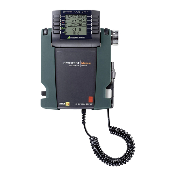
- Page 1 Operating Instructions PROFITEST BASE TECH 3-349-470-03 Test Instruments for IEC 60364.6 / DIN VDE 0100 9/4.12...
- Page 2 Test Instrument and Adapter * Refer to section 2.1 on page 5 regarding usage of the test probes. LEDs & connection symbols section 18.1 Control Panel Fixed Function Keys Softkeys ESC: Return to submenu • Parameter selection • Specify limit value MEM: Key for memory functions •...
-
Page 3: Display Panel
Overview of Device Settings and Measuring Functions Relative to Rotary Switch Setting Test Instrument and Adapter Connectors for current clamp / probe Switch Picto- Device Settings 1 Control panel with keys and 15 Current clamp connection 1 position graph Measuring Functions display panel with snap in 16 Current clamp connection 2 descrip-... -
Page 4: Table Of Contents
Table of Contents Page Page Scope of Delivery .............. 4 Measuring the Impedance of Insulating Floors and Walls (standing surface insulation Application ................ 5 impedance Z ) ............... 33 Using Cable Sets and Test Probes ..........5 Overview of Features Included with Measuring Insulation Resistance ......... -
Page 5: Application
Application Using Cable Sets and Test Probes • 2 or 3-pole measuring adapter included The PROFITEST measuring and test instrument is used for ASTER • 2-pole measuring adapter with 10 m cable as optional acces- rapid and efficient testing of protective measures in sory: PRO-RLO II (Z501P) accordance with DIN VDE 0100, part 600:2008 (Erection of •... -
Page 6: Safety Features And Precautions
Safety Features and Precautions Note This instrument fulfills the requirements of applicable European We recommend rechargeable NiMH batteries. See also section and national EC guidelines. We confirm this by affixing the CE 19.2 on page 56 concerning charging and the battery charger. mark. -
Page 7: Device Settings
Device Settings SETUP Menu Selection for Operating Parameters LED and LCD test menu Rotary switch balancing menu Display: date / time and battery test Display: automatic shutdown Brightness/contrast menu, of the tester after 45 sec. time, language, profiles Display: automatic shutdown Software revision level, of display illumination after 15 sec. - Page 8 Menu Selection for Operating Parameters LED and LCD test menu Rotary switch balancing menu Display: date / time and battery test Display: automatic shutdown Brightness/contrast menu, of the tester after 45 sec. time, language, profiles Display: automatic shutdown Software revision level, of display illumination after 15 sec.
- Page 9 Significance of the Individual Parameters Attention! Data Loss when changing lan- On-time Test Instrument guage, profiles or reset to default With this function, you can select the time interval after which the settings! test instrument switches off automatically. This selection has a Save your measurement data significant effect on the service life and the charging condition of to a PC before pressing the...
-
Page 10: General Instructions
General Instructions Measurement Value Display and Memory The following appear at the display panel: Connecting the Instrument • Measurement values with abbreviations and units of measure For systems with earthing contact sockets, connect the • Selected function instrument to the mains with the test plug to which the •... -
Page 11: Help Function
Help Function The following information can be displayed for each switch position and basic function after it has been selected with the rotary selector switch: • Wiring diagram • Measuring range • Nominal range of use and Measuring Uncertainty • Nominal value Ð... -
Page 12: New! Freely Adjustable Parameters Or Limit Values
New! New! Freely Adjustable Parameters or Limit Values Two-Pole Measurement with Rapid or Semiautomatic Polarity Reversal In addition to the fixed values, additional values can be freely adjusted within specified limits for certain parameters provided Rapid, semiautomatic two-pole measurement is available for the symbol Menu EDIT (3) appears at the end of the list of setting following tests. -
Page 13: Measuring Alternating Voltage And Frequency
Measuring Alternating Voltage and Frequency 6.1.2 Voltage between L – PE, N – PE and L – L for connection of 2-pole adapter Select the Measuring Function Repeatedly press the sofkey shown at the left in order to switch back and forth between the country- specific plug insert, e.g. -
Page 14: 3-Phase Measurement (Line-To-Line Voltage) And Phase Sequence
3-Phase Measurement (Line-to-Line Voltage) and Phase Testing RCDs Sequence The testing of residual current devices (RCDs) includes: • Visual inspection Connection • Testing • Measurement The measuring adapter (2-pole) is required in The test instrument is used for testing and measurement. order to connect the instrument, and is Measuring Method... -
Page 15: Measuring Contact Voltage
Test Standard Measuring Contact Voltage (with reference to nominal residual current) with Nominal Residual Current and The following must be substantiated per DIN VDE 0100, Tripping Test with Nominal Residual Current part 600: 2008: – Contact voltage occurring at nominal residual current may not Select the Measuring Function exceed the maximum allowable value for the system. - Page 16 1) Measuring Contact Current Without Tripping the RCD 2) Tripping Test after the Measurement of Contact Voltage Ð Press the I key before on-time has expired (30 seconds). N Measuring Method The instrument uses a measuring current of only 1/3 nominal The tripping test need residual current for the determination of contact voltage U IN...
-
Page 17: Special Testing For Systems And Rccbs
Special Testing for Systems and RCCBs 7.2.1 Testing Systems and RCCBs with Rising Residual Current (alternating current) for RCDs type A, AC and B Contact voltage: Measuring Method The instrument generates a continuously rising residual current of (0.3 ... 1.3) within the system for the testing of RCDs. -
Page 18: Testing Rccbs With 5 I
7.2.3 Testing RCCBS with 5 7.2.4 Testing RCCBs which are Suited for N Pulsating DC Residual Current The measurement of time to trip is performed here with 5 times nominal residual current. In this case, RCCBs can be tested with either positive or negative half-waves. -
Page 19: Testing For Special Rcds
Testing for Special RCDs Tripping Test Ð Press the I key. The RCCB is tripped. Blinking bars appear N 7.3.1 Systems with Type RCD-S Selective RCDs at the display panel, which is followed by the display of time to trip t and earthing resistance R Selective RCDs are used in systems which include two series connected RCCBs which are not tripped simultaneously in the... -
Page 20: Srcds, Prcd-S (Schukomat, Sidos Or Comparable)
Measuring Method 7.3.3 SRCDs, PRCD-S (SCHUKOMAT, SIDOS or comparable) The following can be measured, depending upon the measuring RCCBs from the SCHUKOMAT, SIDOS series, as well as others method: which are of identical electrical design, must be tested after • Time to trip t : tripping test with nominal residual current I selecting the corresponding parameter. -
Page 21: 7.3.4 Type G Or R Rccbs
7.3.4 Type G or R RCCBs In addition to standard RCCBs and selective RCDs, the special Set Parameters – 5 Times Nominal Current characteristics of the type G RCCB can also be tested with the instrument. The type G RCCB is an Austrian specialty and complies with the ÖVE/ÖNORM E 8601 device standard. -
Page 22: Testing Residual Current Circuit Breakers In Tn-S Systems
Testing Residual Current Circuit Breakers in TN-S Systems Testing Residual Current Circuit Breakers (RCDs) in IT Systems with High Wiring Capacitance (e.g. in Norway) Connection The system type (TN/TT or IT) can be adjusted for U N IN RCD tests and for earth resistance measurements (R For measurements in IT systems, a probe is indispensable as the resulting contact voltage U cannot be measured without a... -
Page 23: Testing Of Breaking Requirements Overcurrent Protective Devices, Measurement Of Loop Impedance And Determination Of Short-Circuit Current
Testing of Breaking Requirements Overcurrent Select the Measuring Function Protective Devices, Measurement of Loop Impedance and Determination of Short-Circuit L-PE Current (functions Z and I L-PE Testing of overcurrent protective devices includes visual inspection and measurement. The PROFITEST is used to to ASTER perform measurements. -
Page 24: Measurements With Suppression Of Rcd Tripping
Measurements with Suppression of RCD Tripping Semiautomatic Measurement in Multi-Pole Systems 2-pole measurement (selection only relevant for report generation): 8.1.1 Measurement with Positive Half-Waves (only PROFITEST TECH Measurements between Lx-PE / N-PE / Lx-N / Lx-Ly / AUTO* Measurement by means of half-waves plus DC makes it possible where x, y = 1, 2, 3 to measure loop impedance in systems which are equipped with * See section 5.8 regarding AUTO parameter. -
Page 25: Evaluation Of Measured Values
Evaluation of Measured Values Measuring Line Impedance (Z function) The maximum allowable loop impedance Z which may be dis- L-PE Measuring Method (internal line resistance measurement) played after allowance has been made for maximum operating Supply impedance Z is measured by means of the same measurement error (under normal measuring conditions) can be method used for loop impedance Z (see section 8 on page... - Page 26 Significance and Display of U (per DIN VDE 100, part 600) Voltage drop from the intersection of the distribution network and the consumer system to the point of connection of an electrical power consumer (electrical outlet or device connector terminals) Limit value: should not exceed 4% of nominal line voltage.
-
Page 27: Earthing Resistance Measurement
Earthing Resistance Measurement (function R Characteristic Values of Earth Resistance Measurement (Mains Powered) Earthing resistance R is important for automatic shutdown in system sections. It must have a low value in order to assure that • Measuring range 0 ... 10 k high short-circuit current flows, and that the system is shut down Measurement with or without earth electrode voltage depending reliably by the RCCB in the event of a fault. -
Page 28: Measuring With Probe
10.1 Measuring with Probe Earth Resistance Measurement with Probe (Mains Powered) – Connection Circuit Diagram Set parameters q Measuring range: AUTO, Operational earth 10 k (4 mA), 1 k (40 mA), 100 (0,4 A), 10 (> 0.65 A) Earth resistance In systems with RCCBs, resistance and/or test current must Earth resistance via equipotential bonding systems... -
Page 29: Measuring Without Probe
10.2 Measuring Without Probe Earth Resistance Measurement without Probe (Mains Powered) – Connection Circuit Diagram Select the Measuring Function Operational earth Earth resistance Internal resistance Earth resistance via equipotential bonding systems Set parameters Probe resistance q Measuring range: AUTO, Equipotential bonding strip 10 k... -
Page 30: Measuring Earth Electrode Potential (Function U E )
10.3 Measuring Earth Electrode Potential (function U Earth Resistance Measurement with Probe (Mains Powered) – Connection Circuit Diagram This measurement is only possible with a probe, see section 10.1. Set parameters Earth electrode potential U is the voltage which occurs at the q Measuring range: 10 ... -
Page 31: Selective Earth Resistance Measurement With Accessory Current Clamp Sensor
10.4 Selective Earth Resistance Measurement with Accessory Current Clamp Sensor As an alternative to the classical measuring method, it is possible to perform measurements with a current clamp sensor. Selective Earth Resistance Measurement (Mains Powered) – Connection Circuit Diagram Key figure below Set parameters at the test instrument q Connection type: 2-pole adapter + clamp sensor Operational earth... - Page 32 Start Measurement If you have changed the transformer ratio at the test instrument, a popup window appears prompting you to enter this new setting to the connected current clamp sensor as well. i: Prompt regarding currently selected transformer ratio at the tester : Selective earth resistance measured with clamp Clamp...
-
Page 33: Measuring The Impedance Of Insulating Floors And Walls (Standing Surface Insulation Impedance Zst )
Measuring the Impedance of Insulating Floors and Walls (standing surface insulation impedance Z Measuring Method The instrument measures the impedance between a weighted metal plate and earth. Line voltage available at the measuring location is used as a source of alternating voltage. The equivalent circuit of Z is regarded as a shunt connection. -
Page 34: Measuring Insulation Resistance
Measuring Insulation Resistance Limit Values for Constant Test Voltage 12.1 General Limit value: Select the Measuring Function < Limit value R Connection Via 2-pole adapter Limit Currents for Ramp Function or test plug! Limit value: I > I Limit STOP q Test Voltage Note... - Page 35 q Pole Selection Report Entry Special Condition for Insulation Resistance Measurement The poles between which testing takes place can only be entered here for reporting purposes. The entry itself has no influence on Attention! the actual polarity of the test probes or the pole selection. Insulation resistance can only be measured at voltage-free objects.
-
Page 36: Special Case: Earth Leakage Resistance (Reins )
12.2 Special Case: Earth Leakage Resistance (R Connection and set-up EINS This measurement is performed in order to determine electrostatic discharge capacity for floor coverings in accordance with EN 1081. Select the Measuring Function Set Parameters Ð Rub the floor covering at the point at which measurement is to be performed with a dry cloth. -
Page 37: Testing Meter Start-Up With Earthing Contact Adapter
Testing Meter Start-Up with Earthing Contact Adapter Special Case Start-up of energy consumption meters which are connected Start-up of energy consumption meters which are connected between L and L, or L and N, can be tested with this function. between L and N can be tested with this function. Connection L –... -
Page 38: Measuring Low-Value Resistance Of Up To 100 Ohm (Protective Conductors And Protective Equipotential Bonding Conductors)
Measuring Low-Value Resistance of up to OFFSET ON – Compensation for Extension Cables with up to 10 100 Ohm (protective conductors and protective If extension cables are used, their resistance can be deducted equipotential bonding conductors) automatically from the measurement results. Proceed as follows: According to the regulations, the measurement of low-value = 0.00 ”... - Page 39 Start Measurement Note Measuring Low-Value Resistance Measurement cable and 2-pole measuring adapter resistance is compensated for automatically thanks to the four conductor method and does not effect measurement results. However, if an extension cable is used its resistance must be measured and deducted from the measurement results.
-
Page 40: Measurement With Accessory Sensors
Measurement with Accessory Sensors Set Parameters The transformation ratio parameter must be correspondingly set 15.1 Measuring Current with a Current Sensor Clamp at the test instrument depending upon the respectively selected measuring range at the current sensor clamp. Biasing, leakage and circulating current up to 1 A, as well as leakage current up to 1000 A can be measured with the help of special current sensor clamps, which are connected to sockets (15) and (16). -
Page 41: Database
Database 16.2 Transferring Distributor Structures The following data transfer operations are possible: 16.1 Creating Distributor Structures, General • Transfer a distributor structure from the PC to the test A complete distributor structure with data for electrical circuits and instrument. RCDs can be created in the PROFITEST test instrument. -
Page 42: Structure Creation (Example For Electrical Circuit)
Symbols of a Distributor Structure / Topology Symbol Meaning A check mark measurement symbol next to a structural element means that all Processing of selected structural element measurements within the respective hierarchy have been passed. Measurement symbol x: at least one measurement has not been passed. No measurement symbol: no measurement has been performed so far. -
Page 43: 16.3.2 Searching For Structural Elements
Select a new object from a list. 16.3.2 Searching for Structural Elements Scroll up scroll up Scroll down scroll down Acknowledge selection. Acknowledge selection / Change level Display object number or ID number next page Select an object from the list with the cursor keys and acknowledge with the Enter () key. -
Page 44: Data Storage And Reporting
Retrieving Saved Measured Values Ð Switch to the distributor structure by pressing the MEM key and to the requested electrical circuit via the cursor keys. Search for ID number ÐSwitch to page 2 by pressing the key shown at the right: Search for text Search for ID number or text... -
Page 45: 16.4.1 Using Barcode And Rfid Readers
Data Evaluation and Reporting with the ETC Software 16.4.1 Using Barcode and RFID Readers After all measurements have been completed, the structure is Searching for a Barcode which has Already been Read In transferred along with the pertinent data to ETC. Comments can The procedure can be started from any selector switch setting then be added to the individual measurements. -
Page 46: Operating And Display Elements
Operating and Display Elements (7) Alligator Clip (plug-on) (8) Test Probes Test Instrument and Adapter The test probes comprise the second (permanently attached) and third (plug-on) poles of the measuring adapter. A coil cable connects them to the plug-on portion of the measuring adapter. (1) Control Panel –... - Page 47 (17) Probe Connector Socket Control Panel – LEDs The probe connector socket is required for the measurement of probe voltage U , earth electrode voltage U , earthing MAINS/NETZ LED S-PE resistance R and standing surface insulation resistance. This LED is only functional when the instrument is switched on. It It can be used for the measurement of contact voltage during has no function in voltage ranges U and U...
-
Page 48: Characteristic Values
Characteristic Values Connections Input Func- Measured Reso- Measuring Intrinsic Clamp Plug Display Range Impedance/ Measuring Range Nominal Values 2-Pole 3-Pole tion Quantity lution Uncertainty Uncertainty Insert Probe MFLEX Test Current Adapter Adapter WZ12C Z3512A P300 (2% rdg.+5d) (1% rdg.+5d) 0 ... 99.9 V 0.1 V L-PE 90 ... - Page 49 Connections Input Func- Measured Reso- Measuring Intrinsic Clamp Plug Display Range Impedance/ Measuring Range Nominal Values 2-Pole 3-Pole tion Quantity lution Uncertainty Uncertainty Insert Probe MFLEX Test Current Adapter Adapter WZ12C Z3512A P300 (10% rdg.+8d) (4% rdg.+7d) 0 ... 99.9 mA 0.1 mA 5 ...
- Page 50 Ambient Conditions Accuracy 0 ... + 40C C ... +50C Operation –10 –20 C ... +60 C Storage (without rechargeable batteries) Relative Humidity Max. 75%, no condensation allowed Elevation Max. 2000 m Mechanical Design Display Multiple display with dot matrix, 128 x 128 pixels Dimensions W x L x D = 260 x 330 x 90 mm...
-
Page 51: Led Indications, Mains Connections And Potential Differences
18.1 LED Indications, Mains Connections and Potential Differences Status Test Meas. Selector Switch Function / Meaning Plug Adapter Position LED Indications N / I Correct connection, measurement enabled NETZ/ lights up green MAINS L-PE N / I N conductor not connected, NETZ/ ... - Page 52 Status Test Meas. Selector Switch Function / Meaning Plug Adapter Position Short between L1 and L3 displayed (3-phase measurement) Short between L2 and L3 displayed (3-phase measurement) is dis- Phase conductor L1 missing played (3-phase measurement) is dis- Phase conductor L2 missing played (3-phase measurement) is dis-...
- Page 53 Status Test Meas. Selector Switch Function / Meaning Plug Adapter Position RCD is tripped too early, or is defective. L-PE Remedy: Test with positive or negative half-wave. RCD tripped during contact voltage measurement. N Remedy: Check selected nominal test current. Externally accessible fuse is defective.
- Page 54 Status Test Meas. Selector Switch Function / Meaning Plug Adapter Position > Z OFFSET Offset value greater than the measured value at the power consuming system OFFSET measurement not advisable Remedy: check system Contact problem or fuse is defective Remedy: check test plug or measuring adapter for correct seating in the test plug or replace fuse.
- Page 55 Status Test Meas. Selector Switch Function / Meaning Plug Adapter Position Database and Entry Operations The selected parameters do not make sense in combination with other, previously set parameters. The selected parameters will not be accepted. Remedy: enter other parameters Please enter a designation (alphanumeric).
-
Page 56: Maintenance
Maintenance 19.3 Fuses If a fuse has blown due to overload, a corresponding error 19.1 Firmware Revision and Calibration Information message appears at the display panel. The instrument’s voltage measuring ranges are nevertheless still functional. See section 4.6 Replacing Fuses 19.2 Rechargeable Battery Operation and Charging Check to make sure that no leakage has occurred at recharge-... -
Page 57: Appendix
Appendix 20.1 Tables for the determination of maximum or minimum display values under consideration of maximum instrument operating uncertainty: Table 1 Table 3 . (full-wave) / Z . (+/- half-wave) M L-PE L-PE () () Limit Min. Limit Min. Limit Max. - Page 58 Table 5 k Limit Min. Value Display Value >999 Table 6 Minimum Display Values for Short-Circuit Current for the determination of nominal current for various fuses and breakers for systems with nominal voltage of U =230 V Nominal Low Resistance Fuses With Circuit Breaker and Line Switch Current I in accordance with the DIN VDE 0636 series of...
-
Page 59: Testing Electrical Machinery Per Din En 60204 - Applications, Limit Values
20.2 Testing Electrical Machinery per DIN EN 60204 – Applica- Special Tests tions, Limit Values • Pulse control mode for troubleshooting (with PROFITEST 204HP/HV only) The PROFITEST 204+ test instrument has been developed for test- ing electrical machinery and controllers. After the standard was •... -
Page 60: Periodic Testing Per Bgv A3
20.3 Periodic Testing per BGV A3 – Limit Values for Electrical Systems and Equipment Limit Values per DIN VDE 0701-0702 Maximum Permissible Limit Values for Protective Conductor Resistance for Connector Cables with Lengths of up to 5 m Open- Test Standard Test Current Housing –... -
Page 61: List Of Abbreviations And Their Meanings
20.4 List of Abbreviations and their Meanings Current Breaking current RCCBs (residual current device / RCD) Leakage current (measured with current transformer Tripping current clamp) Nominal residual current N Measuring current Rising test current (residual current) Nominal current PRCD Portable residual current device Test current PRCD-S : with detection and/or monitoring of protective conductor... -
Page 62: Index
20.5 Index Symbols ................... 5 Abbreviations ................61 Testing Electrical Machinery ............59 per BGV A3 ..............60 Bibliography ................63 with Biasing Current ............18 Type G RCCB ................ 21 Contact Voltage ..............16 Current Sensor Clamp Voltage Drop in % (Function ZL-N) ......... 26 Measuring Ranges ............ -
Page 63: Bibliography
20.6 Bibliography Further Literature in German Title Author Publisher Issue / Statutory Source Documents Order no. Betriebs Sicherheits Verordnung (BetrSichV) (German occupational safety leg- islation) Wiederholungs- Bödeker, K.; Kin- Hüthig & Pflaum 2007 issue prüfungen nach DIN VDE dermann, R.; Matz, www.vde-verlag.de VDE order num- Regulations issued by the accident insurance carriers... -
Page 64: Repair And Replacement Parts Service Calibration Center And Rental Instrument Service
Repair and Replacement Parts Service Recalibration Calibration Center* and Rental The respective measuring task and the stress to which your mea- suring instrument is subjected affect the ageing of the compo- Instrument Service nents and may result in deviations from the guaranteed accuracy. If required please contact: If high measuring accuracy is required and the instrument is fre- GMC-I Service GmbH...
Need help?
Do you have a question about the PROFITEST MBASE MTECH and is the answer not in the manual?
Questions and answers