
Related Manuals for Gossen MetraWatt METRISO C


Summary of Contents for Gossen MetraWatt METRISO C
- Page 1 Operating Instructions ® METRISO C-GB int. 3-349-087-03 Insulation, Resistance and Contact Current Measuring Instrument 12/11.08...
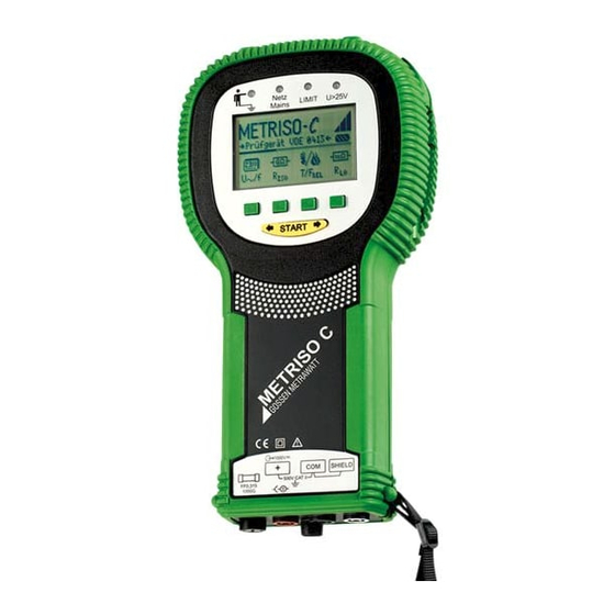
- Page 2 ® ® METRISO C Measuring and Test Instrument METRISO C Control Panel and Display Infrared interface Temperature and humidity measuring adapter Z541A Operating and display unit Indicator lamps Netz LIMIT Mains U>25V Battery level display The scroll bar indicates which Contact surface menu is currently open.
- Page 3 ® PC software WinProfi for communication with METRISO The PS3 CD-ROM includes the software WinProfi with the following con- tent and functions: • up-to-date test instrument software – for loading another language – for loading software version updates, • Exchange of measured data between test instrument and PC •...
-
Page 4: Table Of Contents
Contents Page Contents Page Applications ..................5 Setting the Limit Value .................. 21 Measuring Contact Current ............22 Safety Features and Precautions ............5 10.1 Setting the Limit Value .................. 22 Initial Start-Up .................6 Characteristic Values ..............23 Battery Test ....................6 Installing and Replacing Batteries ..............6 List of Abbreviations and their Meanings ........25 User Guide in a Different Language ..............6 Maintenance .................25... -
Page 5: Applications
Applications Safety Features and Precautions ® This instrument fulfills the requirements of the applicable European and The METRISO C electronic measuring and test instrument is manufac- national EC guidelines. We confirm this with the CE marking. The relevant dec- tured and tested in accordance with safety regulations IEC/EN 61010-1/ laration of conformity can be obtained from GMC-I Messtechnik GmbH. -
Page 6: Initial Start-Up
Initial Start-Up User Guide in a Different Language By performing a software update it is possible to load another language Battery Test for the user guide than the one included in the scope of supplies. Any lan- Five battery symbol segments ranging from depleted to fully charged guage currently available is proposed for choice when WinProfi is being continuously indicate the current battery level at the main menu. - Page 7 Default Settings – Last Used Settings Setting On-Time, Manual Shutdown A selection can be made here as to whether the menus will be displayed according to the default settings, or if the last opened menus should be displayed. ➭ Activate the Setup key. ➭...
- Page 8 Background Illumination and Contrast Setting the Clock LCD Illumination Contrast high ➭ ➭ Activate the Display key. Activate the Time key. ➭ ➭ In order to extend battery service life, display illumination can be The cursor appears at the first digit in the date. Enter the desired switched off entirely.
-
Page 9: Downloading A Software Update, Managing Report Data
Downloading a Software Update, Managing Report Data A Install WinProfi to the PC and Start the Program ➭ If you require an updated test instrument software, it can be downloaded First install the software to your PC. with the help of WinProfi PC software. The data file with the desired soft- Insert the CD into the CD drive, for example drive E. - Page 10 B Prerequisites for Software Update or Data Exchange C Transmission of a Software Update to the Test Instrument ® ➭ Find the interface to which the METRISO C is connected. ➭ PC: Select the Update All function from the Update menu. Follow the instructions which appear at the monitor.
- Page 11 D Managing Report Data • Edit or transmit report templates ® ➭ Connect the METRISO C test instrument with your PC via the IrDa- USB converter ➭ Start WinProfi. ➭ Switch on the test instrument. ® ➭ Set the on-time period of the METRISO C to „>>>>>“, to give you enough time for adjusting the settings in WinProfi before the test in- strument switches off again automatically, see chapter 3.3.
-
Page 12: General Operation
KS-C values are displayed in digital format until the next measuring sequence is tance measurement cable for METRISO C, for (Z541F) started, or until the instrument switches itself off automatically. measurements in the GΩ range“, see connection If the measuring range upper value is exceeded, the upper value is dis- diagram). -
Page 13: Measuring Insulation Resistance
Measuring Insulation Resistance Insulation resistance can only be measured at voltage-free objects. If mains voltage or an interference voltage is applied to the measurement cables, insulation resistance is not measured and the Netz/Mains lamp Attention! lights up. Do not touch the connector terminals at the instrument during ☞... -
Page 14: Insulation Measurement With Adjustable Test Voltage
Insulation Measurement with Adjustable Test Voltage Measurement with Rising Test Current A DC test voltage within a range of 50 to 1000 V can be selected with the The “U ” function can be used for the detection of weak points in function for measurements at sensitive components and in insulation, as well as for the determination of response voltage at voltage systems equipped with voltage limiting components. -
Page 15: Database Functions
➭ Database Functions With the help of the softkeys, entries can be made to the BUILDING, DISTRIBUTOR CABINET, RCD No. and CIRCUIT fields one after the other, and The displayed measurement data for each measurement can be saved to a designation can be entered for the electrical circuit. an internal database, with or without a comment. -
Page 16: Saving Measurement Values - Store Function
☞ Saving Measurement Values – STORE Function ➭ Note Start the respective measurement. The STORE key is displayed after the measurement instead of the INFO key. The test reports included with the analysis software (e.g. PS3) The STORE key is not displayed until after a given amount of time has have separate fields for measured values R (without load) and ISON... -
Page 17: Deleting A Data Record From Within A Memory Address - View Function
6.3.2 Deleting a Memory Address – Data Function ➭ Select Data. ➭ Enter blanks to the data fields BUILDING, DISTRIBUTOR CABINET, RCD No. and CIRCUIT. After all of these fields have been entirely overwritten with blanks,they are displayed as inverse images. In case a measurement value is missing for the currently selected current circuit, perform the measurement and the value will be immediately START... -
Page 18: Delete All Memory Addresses - Data Function
➭ 6.3.3 Delete All Memory Addresses – Data Function By simultaneously activating O and K all data that have been saved are deleted from memory. The bar graph to the right of the parameter Up to 250 data records can be stored to memory. The memory is full „MEMORY:“... -
Page 19: Measuring Alternating Voltage
➭ Measuring Alternating Voltage Press the T/F key. The adapter is activated via the interface. ➭ Select the desired temperature unit of measure, ° C or ° F, with the Sinusoidal alternating voltage within a frequency range of 40 to 200 Hz can be measured with the test instrument. -
Page 20: Measuring Low-Value Resistance (To 100 Ω)
Measuring Low-Value Resistance (to 100 Ω) Automatic Polarity Reversal – AUTO± Function According to the regulations, measurement of low-value resistance at With automatic polarity reversal, the instrument performs measurement protective conductors, earth conductors and bonding conductors must first in one direction and then in the other, after the measuring sequence be performed with (automatic) measuring voltage polarity reversal, or with has been started. -
Page 21: Compensation For Measurement And Extension Cables (Up To 10 Ω)
Compensation for Measurement and Extension Cables (up to 10 Ω) Measurement and extension cable ohmic resistance can be subtracted automatically from the measurement results. Proceed as follows: ➭ Activate the + / − key in the menu bar. ➭ Short circuit the two test probes at the ends of the measuring cables, with interconnected extension cables if used. -
Page 22: Measuring Contact Current
Measuring Contact Current Voltage at the Device Under Test: U > 25 V Substantiation of the absence of voltage can be provided by means of contact current measurement (DIN VDE 0701 part 240). START ➭ Briefly press the START key in order to start the measurement. Contact voltage U is measured and displayed. -
Page 23: Characteristic Values
Characteristic Values Measured Nominal Values / Measuring Display Range Test Current Measuring Range Intrinsic Uncertainty Quantity Impedance Uncertainty 20 kΩ … 10.0 GΩ ±(5% rdg. + 3 d) ±(7% rdg. + 3 d) = 100 V 0.20 MΩ … 10.0 GΩ ±(5% rdg. - Page 24 Overload Capacity Protection Housing IP 52 per DIN VDE 0470 Part 1/EN 60529 with pressure compensating diaphragm made of Electronic protection disables start-up if microporous ePTFE, non-aging, diam. 8 mm in interference voltage is present. battery compartment cover 500 V~ continuous Extract from table on the meaning of IP codes Electrical Safety IP XY...
-
Page 25: List Of Abbreviations And Their Meanings
Table for the determination of maximum display values for low resistances by Maintenance making allowances for the instrument’s measuring error. 13.1 Self-Test Maximum Maximum Limit Value Limit Value Display Value Display Value 0.15 Ω 0.11 Ω 0.20 Ω 0.16 Ω 5.00 Ω... -
Page 26: Battery Operation
➭ Illum: Press the Test key twice in order to activate and deactivate Connect the NA102 battery charger to the charging socket with the display illumination. 3.5 mm jack plug. Set the voltage selector switch at the NA102 to 9 V. ➭... -
Page 27: Housing
Replacing Fuses Repair and Replacement Parts Service DKD Calibration Center* and Rental Instruments Service ➭ Remove the cap for the respective fuse with the help of a suitable tool If required please contact: (e.g. screwdriver) by pressing and turning counterclockwise. GMC-I Service GmbH Service Center Attention! -
Page 28: Product Support
Product Support If required please contact: GMC-I Messtechnik GmbH Product Support Hotline Phone: +49 911 8602-0 Fax: +49 911 8602-709 E-Mail support@gossenmetrawatt.com Edited in Germany • Subject to change without notice • A pdf version is available on the Internet Telefon+49 911 8602-111 GMC-I Messtechnik GmbH Telefax +49 911 8602-777...
Need help?
Do you have a question about the METRISO C and is the answer not in the manual?
Questions and answers