Sleipner SH320 Installation Manual
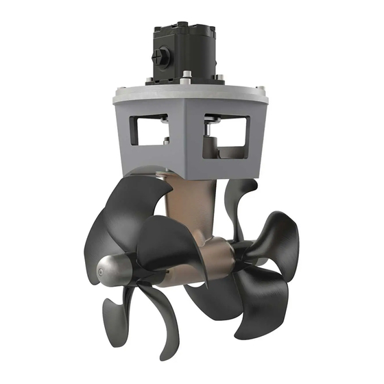
Hydraulic thruster
Hide thumbs
Also See for SH320:
- Installation manual (28 pages) ,
- Installation manual (24 pages) ,
- User manual (16 pages)

Related Manuals for Sleipner SH320


Summary of Contents for Sleipner SH320
- Page 1 Installation Guide For Hydraulic Thruster Models SH320 DOCUMENT ID: SLEIPNER AS 5938 REVISION: P.O. Box 519 DATE: N-1612 Fredrikstad 2021 Norway LANGUAGE: www.sleipnergroup.com...
-
Page 2: Table Of Contents
Installation instructions Products Planning Considerations and Precautions......... 3 Thruster Measurements ............4 SM140009 | SH320/300TC-BA16 - SH320 Tunnel thruster, BA16 SM908035 | SH320/300TC-BA19 - SH320 Tunnel thruster, BA19 Thruster Specifications ............. 5 SM905347 | SH320/300TC-U14 - SH320 Tunnel thruster, U14 Technical Specifications ............ -
Page 3: Planning Considerations And Precautions
If installing S-link products DO NOT connect any other control equipment to the S-link controlled products except Sleipner original S-link products or via a Sleipner supplied interface product made for interfacing with other controls. Any attempt to directly control or at all connect into the S-link control system without the designated and approved interface will render all warranties and responsibilities for the complete line of Sleipner products connected void and null. -
Page 4: Thruster Measurements
Propeller position will vary with each thruster model Twin Propeller The gear leg/ propeller(s) must never extend out of the tunnel Tunnel centre line MG_0078 Thruster Measurements MC_0186 *320 Measurement Measurement description code inch Internal tunnel diameter 11.81 Motor Height 9.65 Width 10.16... -
Page 5: Thruster Specifications
Thruster Specifi cations MC_0145 Description * 320 Light duty thrust up to (kg * lbs) 320kg * 705lbs Heavy duty thrust up to (kg * lbs) 270kg * 594lbs Typical Boat Size (m * ft) 13m - 23m * 42ft - 75ft Propulsion System Twin Counter Rotating Power (kw * Hp) -
Page 6: Positioning Of The Tunnel/ Thruster
Pivot point important Lowered rotation power performance Stronger rotation power performance Water line Ø min 1/4 Ø (Recommended) min 1/4 Ø (Recommended) MG_0001 Positioning of the tunnel / thruster MC_0003 Aim to install the thruster as far forward as possible (1) Due to the leverage effect around the boats’... -
Page 7: Tunnel Length
Do not allow the variable length of the tunnel walls to vary in length excessively. EG. the top tunnel wall is x 4 longer than the bottom wall. Water flow must have space to "straighten" itself for best Cavitation performance. -
Page 8: Tunnel Installation In Sailboats
Pos. A Pos. B MG_0004 Tunnel installation in sailboats MC_0003 Some sail boats have a flat bottom and shallow draft in the bow section. This can make installing the thruster as far forward from the boats main pivot point diffi... -
Page 9: Water Deflection
High water force while underway High water force while underway from wave contact MG_0003 Water Deflection MC_0003 A possible problem in sail boats or fast powerboats is that a non-rounded surface can generate drag from the back face of the tunnel, as it creates “flat”... -
Page 10: Tunnel Ends
R = 0,1 x D (10%) Cavitation Angled tunnel ends for steel/ aluminium hulls MG_0002 Tunnel Ends MC_0003 Rounded tunnel ends will maximise thrust and minimise noise and cavitation. For best performance round the tunnel connection to the hull-side as much as possible. The minimum rounding has a radius of 10% of the diameter of the tunnel. -
Page 11: Tunnel Installation
8 x layers of fiberglass and resin 8 x layers of fiberglass and resin MG_0005 Tunnel Installation MC_0003 IMPORTANT We recommend that a professional does the fi breglass, steel or aluminium fi tting of the tunnel. These instructions are only general instructions and do not explain in any way the details of fi... - Page 12 Hull Hull Layers of Layers of fiberglass fiberglass and resin and resin Tunnel Additional Layers of Hull fiberglass and resin Welding Tunnel *Fiberglass *Steel/ Hull Aluminium Hull Hull R = D x 0,1 Layers of fiberglass R = D x 0,1 and resin Tunnel Additional Layers of...
-
Page 13: Stern Tunnel Installation
Stern Tunnel Installation MC_0003 Stern thruster installation has extra considerations and precautions and thruster installation procedures. See the attached manual supplied in the stern thruster kit Stern Thruster Installation Guide SH 320 5938 2021... -
Page 14: Hydraulic Thruster Installation Considerations And Precautions
If installing S-link products DO NOT connect any other control equipment to the S-link controlled products except Sleipner original S-link products or via a Sleipner supplied interface product made for interfacing with other controls. Any attempt to directly control or at all connect into the S-link control system without the designated and approved interface will render all warranties and responsibilities for the complete line of Sleipner products connected void and null. -
Page 15: Technical Specifications
39.9 43.7 Max. thrust: 182kg USG-PSI 9.14 2480 10.54 3321 11.55 3973 Max. thrust: 228kg L/min -Bar 33.8 39.0 43.6 SH320 Max. thrust: 211kg BA16 USG-PSI 8.93 2494 10.30 3335 11.52 4162 Max. thrust: 269kg L/min -Bar 41.0 47.3 52.9 Max. -
Page 16: Technical Requirements / Hydraulic Hose Connections To Motor
07.03.2014 07.03.2014 Hyd. motor 16 ccm Copyright All rights reserved Copyright All rights reserved Title Title Hyd. motor 16 ccm Hyd. motor 16 ccm SLEIPNER MOTOR AS Part nr Weight Size Scale Edition Sheet SLEIPNER MOTOR AS SLEIPNER MOTOR AS... -
Page 17: Gear Leg & Motor Bracket Installation
2 - 4 PORT STARBOARD Measurement Boats ØC SH 320 Boats centre line Description centre line inch Tunnel ØA 2.05 centre line 1.89 Tunnel ØC 0.43 centre line ØA Stern PORT STARBOARD Gasket Ensure propeller turns without obstruction Apply MS Polymer sealant or equal to 6 - 7 both sides of the... -
Page 18: Propeller Installation
Drive Pin Propeller Washer Lock Nut Anti-fouling Anode Apply Loctite 243 or similar Anode Holding Screw MG_0033 Propeller Installation MC_0264 ! Please refer to the graphic for special considerations relating to your model ! Centre the drive pin and Insert the propeller onto the shaft spine. Rotate the propeller until the drive pin aligns with the internal slot in the propeller. -
Page 19: Motor Installation
IMPORTANT Ensure the holding key, teeth and coupling are aligned when fitted FASTEN (33 Nm) (24 lb/ft) Motor shaft teeth IMPORTANT Apply seawater resistant grease on Holding Key shafts and gear leg before fitting the flexible coupling MG_0149 Motor Installation MC_0109 ! Please refer to the graphic for special considerations relating to your model ! Install the motor onto the motor bracket ensuring the couplings are engaged together correctly (top and bottom). -
Page 20: S-Link Planning & Precautions
- Round, compact and waterproof plugs with unique keying and colour coding to avoid faulty hookup. - An unlimited number of commands or information transfer on a single cable. - Proprietary Sleipner commands but built 100% on NMEA 2000 standard. Routing the Backbone: Keep routing backbone spur cables to a minimum. -
Page 21: Control Panel Installation
4x SCREWS Ø 4.5 mm Ø 4.5 mm 75.7 mm 58 mm 67 mm GASKET Ø 4.5 mm Ø 4.5 mm Ø 4.5 mm External alarm / buzzer connection (S-link) Supply + 12V / 24V DC Internal fuse / relay External alarm buzzer 12V / 24V DC - max 0,5A MG_0063... -
Page 22: Checklist For Hydraulic Thrusters
Checklist for Hydraulic Thrusters MC_0049 ..Propeller is fastened correctly to the shaft... Propeller turns freely in tunnel... Lower-unit is fi lled with gear oil... Oil-drain screw is tightened and the copper seal is present... The anode holding screw is tightened well with thread glue... -
Page 23: Service And Support
10. This warranty gives you specific legal rights, and you may also have other rights which vary from country to country. Patents MC_0024 At Sleipner we continually reinvest to develop and offer the latest technology in marine advancements. To see the many unique designs we have patented visit our website www.sleipnergroup.com/patents SH 320... - Page 24 © Copyright Sleipner Motor AS, 2021 The information given in the document was correct at the time it was published. However, Sleipner Motor AS can not accept liability for any inaccuracies or omissions it may contain. Continuous product improvement may change the product specifi...
Need help?
Do you have a question about the SH320 and is the answer not in the manual?
Questions and answers