Sleipner SE210 Installation Manual
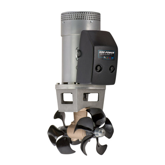
Dc electric thruster
Hide thumbs
Also See for SE210:
- Installation manual (28 pages) ,
- User manual (16 pages) ,
- User manual (16 pages)

Related Manuals for Sleipner SE210


Summary of Contents for Sleipner SE210
- Page 1 Installation Guide For DC Electric Thruster Models SE210 DOCUMENT ID: SLEIPNER MOTOR AS 2663 REVISION: P.O. Box 519 DATE: N-1612 Fredrikstad 2023 Norway LANGUAGE: www.sleipnergroup.com...
-
Page 2: Table Of Contents
Control Panel Installation ..................................23 Post Installtion Checklist ............................... 24 Service and Support ................................25 Product Spare Parts and Additional Resources ........................25 Warranty Statement ................................25 Sleipner Motor AS P.O. Box 519, Arne Svendsensgt. 6-8 N-1612 Fredrikstad, Norway MC_0020 SE210... -
Page 3: Responsibility Of The Installer
• The thruster must NOT be installed in compartments that require ignition proof electric equipment. If necessary, make a separate compartment. (NB: Sleipner Ignition Protected systems are tested and rated accordance with ISO 8846 and can be installed in areas with possible explosive gases.) -
Page 4: Product Measurements
T (max) Maximum tunnel wall thickness 0,35 *Valid for SE & SEP Propeller position will vary with each thruster model Twin Propeller The gear leg/ propeller(s) must never extend out of the tunnel Tunnel centre line MG_0075 SE210 2663 2023... -
Page 5: Product Specifications
/ Hp kg / lbs S2 motor at 2 - 3 min. Duty cycle at 20°c SE210 24V 250 kg / 550 lbs (24V) 210 kg / 462 lbs (21V) 10 kW / 13.15 hp 68 kg / 150 lbs... -
Page 6: Positioning Of The Tunnel / Thruster
(NB: This can be overlooked depending on the installation methods defi ned in this manual.) Pivot point important Lowered rotation power performance Stronger rotation power performance Water line Ø min 1/4 Ø (Recommended) min 1/4 Ø (Recommended) MG_0001 SE210 2663 2023... -
Page 7: Tunnel Length
The gear leg/ propeller(s) must prevent a circular water vacuum Increase tunnel length to protect never extend out of the tunnel cavity between the propeller and the propeller from water forces the hull of the boat. when high-speed cruising. MG_0048 SE210 2663 2023... -
Page 8: Tunnel Installation In Sailboats
This installation is being used by some of the world’s largest sail boat builders and has proven to give little to no speed loss during normal cruising. This can also be an installation method for flat bottomed barges to avoid extremely long tunnels and large oval tunnel openings in the hull. Pos. A Pos. B MG_0004 SE210 2663 2023... -
Page 9: Water Deflection
In the High water force event when the boat is traveling at high speeds it while underway will commonly pound upon the water surface. High water force while underway from wave contact MG_0003 SE210 2663 2023... -
Page 10: Tunnel Ends
This “free” extra thrust in optimal installations be 30 - 40% of the total thrust. (NB: A Sleipner thruster propeller does not produce cavitation at working speed. Therefore, any cavitation and cavitation noise in the tunnel will be caused during improper tunnel installation.) -
Page 11: Tunnel Installation
(NB: Ensure gaps between the tunnel and the hull are completely fi lled with resin/ fi breglass. In areas where you can not access to make layers of resin/ fi breglass, a resin/ fi breglass mixture must be used in that area.) 8 x layers of fiberglass and resin 8 x layers of fiberglass and resin MG_0005 SE210 2663 2023... - Page 12 You must apply gel coat to areas you have grounded/ moulded to make waterproof. These areas allow water access to the hull which is typically not waterproof without these applications outside. (NB: All original Sleipner tunnels are fully waterproof when delivered except in the areas where you have cut and bonded it to the hull.)
-
Page 13: Stern Tunnel Installation
Stern Tunnel Installation MC_0003 For Stern Thruster installation please refer to the supplied manual in your Sleipner product delivery Installation Guide For DC Electric Thruster Models SE80, SE100, SE120, SE130, SE150 Stern Thruster SLEIPNER AS DOCUMENT ID: 222222 REVISION: P.O. Box 519... -
Page 14: Gear Leg & Motor Bracket Installation
SAC 240/250TC SE/SEP/SE IP/SEP IP 250/300TC PORT STARBOARD SE/SEP/SE IP/SEP IP 300/300TC E250/300TC E300/300TC SH300/300TC SH320/300TC SAC320/300TC Bolt plate SH360/300TC SH400/300TC SAC360/300TC SAC400/300TC SH420/386TC SH550/386TC SH700/412 SAC450/386TC SAC520/386TC SAC700/412 Drill centre hole first Smooth surface area MG_0055 SE210 2663 2023... - Page 15 Place top motor bracket and bolt plate to measure the drive shaft has come through the motor bracket at the correct height. Remove the gear leg and propeller for fi nal installation. Gasket Test the propeller turns without Gear leg obstruction with tunnel wall Motor bracket MG_0618 SE210 2663 2023...
- Page 16 10. Fasten the gear leg and the motor bracket with the bolts provided. Tighten to torque as shown. Apply MS Polymer sealant or equal to both sides of the gasket IMPORTANT Motor bracket Do not apply sealant to the bolt holes. /215mm Tunnel Diameter /185mm /250mm Nm lb/ft mm inch Fasten 13,3 MG_0619 SE210 2663 2023...
-
Page 17: Propeller Installation
Port Starboard Drive Pin Find the propeller hand marking on the back side of the propeller mould. Propeller Lock Nut Washer FASTEN 20 Nm 14.75 lb/ft Anti-fouling Anode Apply Loctite 243 or similar Anode Holding Screw MG_0033 SE210 2663 2023... -
Page 18: Motor Installation
IMPORTANT Ensure a minimum of 80% engagement from the motor coupling with the gear leg holding key > 30° Motor FASTEN (33 Nm) (24 lb/ft) IMPORTANT Do not position support on the motor cap. Motor support MG_0312 SE210 2663 2023... -
Page 19: Electrical Installation
Wiring Diagram chapter for an overview. Sleipner offers both manual main switches and Automatic Main Switches (AMS). Sleipner AMS is controlled by the control panel in addition to the option of manual operation. Turning on the control panel also turn on the automatic main switch. When the control panel is turned off the automatic main switch is turned off. -
Page 20: Electrical Reference Guide
2 x 70 2 x 70 2 x 95 2 x 95 2 x 120 210/250TC 500 A SAE: 1064 ANL 400 EN: 940 2 x 2/0 2 x 2/0 2 x 3/0 2 x 3/0 2 x 4/0 SE210 2663 2023... -
Page 21: Manual Main Switch Wiring Diagram 24V Thruster
Thruster Manual Main Switch BATTERY BATTERY The top and bottom wiring diagram is for a dual thruster system, for example a bow and stern installation. 4-wire cable ANL Fuse Thruster Manual Main Switch Fuse BATTERY BATTERY MG_0591 SE210 2663 2023... -
Page 22: Automatic Main Switch Wiring Diagram 24V Thruster
4-wire cable BATTERY The top and bottom wiring diagram is for a dual thruster system, for example a bow and stern installation. Automatic Main Switch Fuse 5-wire cable Thruster ANL Fuse BATTERY Fuse 5A 4-wire cable BATTERY MG_0578 SE210 2663 2023... -
Page 23: Control Panel Installation
Control Panel Installation MC_0398 For Control Panel installation please refer to the Installation Guide accompanying the control panel to be installed. Installation Guide Control Panel SLEIPNER MOTOR AS DOCUMENT ID: REVISION: P.O. Box 519 N-1612 Fredrikstad DATE: Norway www.sleipnergroup.com LANGUAGE:... -
Page 24: Post Installtion Checklist
Correct drive direction as per control panel: ..............................The compartment for the thruster has been isolated from general bilge water and has no obvious or suspected risks for flooding: .................................................................................................................................. Other comments by installer: ........................................................................................................................SE210 2663 2023... -
Page 25: Service And Support
11. This warranty gives you specific legal rights, and you may also have other rights which vary from country to country. Patents MC_0024 At Sleipner we continually reinvest to develop and offer the latest technology in marine advancements. To see the many unique designs we have patented visit our website www.sleipnergroup.com/patents SE210... - Page 26 Notes MC_0037 ..............................................................................................................................................................................................................................................................................................................................................................................................................................................................................................................................................................................................................................................................................................................................................................................................................................................................................................................................................................................................................................................................................................................................................................................................................................................................................................................................................................................................................................................................................................................................................................................................................SE210 2663 2023...
- Page 27 Notes MC_0037 ..............................................................................................................................................................................................................................................................................................................................................................................................................................................................................................................................................................................................................................................................................................................................................................................................................................................................................................................................................................................................................................................................................................................................................................................................................................................................................................................................................................................................................................................................................................................................................................................................................SE210 2663 2023...
- Page 28 © Sleipner Group, All rights reserved The information given in the document was right at the time it was published. However, Sleipner Group cannot accept liability for any inaccuracies or omissions it may contain. Continuous product improvement may change the product specifi cations without notice.
Need help?
Do you have a question about the SE210 and is the answer not in the manual?
Questions and answers