Table of Contents
Advertisement
Advertisement
Table of Contents
Troubleshooting

Related Manuals for HPE OfficeConnect 1920S Series


Summary of Contents for HPE OfficeConnect 1920S Series
- Page 1 HPE OfficeConnect 1920S Switch Series Installation and Getting Started Guide Abstract This guide provides detailed information on how to install and initially configure switches in the HPE OfficeConnect 1920S Switch Series. Part Number: 5200-2835a Published: August 2017 Edition: 1...
- Page 2 HPE OfficeConnect 1920S 48G 4SFP Switch JL382A HPE OfficeConnect 1920S 8G PPoE+ 65W Switch JL383A HPE OfficeConnect 1920S 24G 2SFP PPoE+ 185W Switch JL384A HPE OfficeConnect 1920S 24G 2SFP PoE+ 370W Switch JL385A HPE OfficeConnect 1920S 48G 4SFP PPoE+ 370W Switch...
-
Page 3: Table Of Contents
Contents Switch overview..................5 Overview............................5 Switch hardware features......................5 Network ports........................9 LEDs..........................10 Mode button........................11 Reset button........................11 Power connector.......................11 Switch features..........................12 Installing the switch................13 Installation overview........................13 Fan-free design...........................13 Included parts..........................13 Installation precautions....................... 14 Installation procedure........................15 1. Prepare the installation site..................15 Installation space requirements................15 2. - Page 4 Websites....................32 Support and other resources...............33 Accessing Hewlett Packard Enterprise Support................. 33 Accessing updates........................33 Customer self repair........................34 Remote support.......................... 34 Warranty information........................34 Regulatory information........................35 Documentation feedback......................35 Specifications..................36 Physical............................36 Electrical............................36 Environmental..........................37 Acoustics.............................37 Safety............................37 Standards............................38 Cabling and Technology Information Specifications..............38 Technology Distance Specifications.................39 Mode Conditioning Patch Cord....................
-
Page 5: Switch Overview
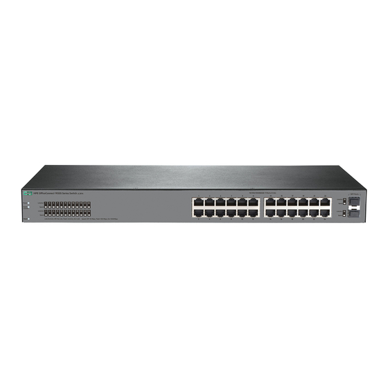
Switch overview Overview The HPE OfficeConnect 1920S Switch Series are multiport switches that can be used to build high- performance switched workgroup networks. These switches are store-and-forward devices that offer low latency for high-speed networking. Three of the switches also support the IEEE 802.3at standard for providing PoE+ power to connected devices. - Page 6 PoE PD port 10/100/1000BASE-T RJ-45 ports Link/Act and Speed LEDs Reset button HPE OfficeConnect 1920S 24G 2SFP Switch (JL381A) Power and Fault/Locator LEDs Link/Act and Speed LEDs SFP slots 10/100/1000BASE-T RJ-45 ports Reset button HPE OfficeConnect 1920S 48G 4SFP Switch (JL382A)
- Page 7 Power and Fault/Locator LEDs PoE+ ports 1-4 Link/Act and Mode LEDs 10/100/1000BASE-T RJ-45 ports Reset button Mode button HPE OfficeConnect 1920S 24G 2SFP PPoE+ 185W Switch (JL384A) Power and Fault/Locator LEDs PoE+ ports 1-12 Link/Act and Mode LEDs Switch overview...
- Page 8 SFP slots 10/100/1000BASE-T RJ-45 ports Mode button Reset button HPE OfficeConnect 1920S 24G 2SFP PoE+ 370W Switch (JL385A) Power and Fault/Locator LEDs PoE+ ports 1-24 Link/Act and Mode LEDs SFP slots 10/100/1000BASE-T RJ-45 ports Mode button Reset button HPE OfficeConnect 1920S 48G 4SFP PPoE+ 370W Switch (JL386A)
-
Page 9: Network Ports
LAN Access Points, and other appliances to receive power as well as data over existing LAN cabling. For further information regarding PoE power, see the HPE Power over Ethernet (PoE/PoE+) Planning and Implementation Guide, which is on the Hewlett Packard Enterprise Web site at www.hpe.com/ support/hpesc. -
Page 10: Leds
Cabling SFP Connector 1000-LX Fiber (multimode or single mode) For supported transceivers, visit www.hpe.com/support/hpesc. • In the first textbox, type J4858 (for 100-Mb and Gigabit information). • Select any of the products that display, then click Show selected items. •... -
Page 11: Mode Button
State Meaning Blinking Indicates that there is network activity on the port.If the Link/Act LED is blinking simultaneously with the Fault/Locator LED, it indicates a fault on the port. The blinking behavior (1 second on, 1 second off) is the same as the Fault/Locator LED. -
Page 12: Switch Features
• 8, 24, or 48 auto-sensing 10/100/1000BASE-T RJ-45 ports. • 2 or 4 SFP slots for HPE SFP transceivers (1920S 24G, 1920S 24G PoE+, 1920S 24G PPoE+ 1920S 48G, and 1920S 48G PPoE+ Switches only) • plug-and-play networking—all ports are enabled—just connect the network cables to active network devices and your switched network is operational. -
Page 13: Installing The Switch
Installing the switch Installation overview The 1920S Switches are easy to install. They come with an accessory kit that includes the brackets for mounting the switches in a standard 19-inch telco rack, in an equipment cabinet, and with rubber feet that can be attached so the switches can be securely located on a horizontal surface. -
Page 14: Installation Precautions
1920S 24G, 1920S 24G PPoE+, and 1920S 48G 1920S 48G PPoE+ Switch Switch Kit number 5069-6535 Kit number 5069-5705 • two wall/table mounting brackets • two rack mounting brackets • eight 8-mm M4 screws to attach the mounting • eight 8-mm M4 screws to attach the mounting brackets to the switch brackets to the switch •... -
Page 15: Installation Procedure
Transceivers not on the 1920S approved list are used at your own risk and may void support and warranty. Please see the HPE Warranty terms and conditions. At this point, your switch is fully installed. See the rest of this chapter if you need more detailed information on any of these installation steps. -
Page 16: Verify The Switch Passes Self Test
AC/DC power adapter into a nearby properly grounded electrical outlet. HPE OfficeConnect 1920S 24- and 48-port switches Connect the power cord to the switch and an AC power outlet. HPE OfficeConnect 1920S 8G switch Connect wall plug-in AC/DC power adapter to the switch and then to an AC power outlet. - Page 17 NOTE: The 1920S 24- and 48-port switches do not have a power switch. They are powered on when the power cord is connected to the switch and to a power source. For safety, the power outlet should be located near the switch installation. The switches automatically adjusts to any voltage between 100-127 or 200-240 volts and either 50 or 60 Hz.
-
Page 18: Mount The Switch
Port Link/Act LEDs Power and Fault/Locator LEDs Mode LED When the switch is powered on, it performs a diagnostic self test. The behavior of the LEDs is as follows: During the self test: • Initially, the Power, Fault/Locator, and all port LEDs turn on. •... -
Page 19: Rack Or Cabinet Mounting
• under a table • in a rack or cabinet Rack or cabinet mounting The switches are designed to be mounted in any EIA-standard 19-inch telco rack or communication equipment cabinet. Note that the mounting brackets have multiple mounting holes and can be rotated allowing for a wide variety of mounting options. -
Page 20: Wall Or Under-Table Mounting
Wall or under-table mounting You can mount the 1920S 24- and 48-port switches on a wall with either the front or rear panel facing up. WARNING: For safe operation, please read Installation precautions on page 14 before mounting the switch. Wall mount the switch with the network ports facing up or down. -
Page 21: Horizontal Surface Mounting
1. In the required location, mark the position for the mounting screws. The hole-to-hole distance is 3.54 inch (90 mm). 2. Use a #1 Phillips (cross-head) screwdriver and two of the included 20-mm M4 tap screws. Set the screw heads approximately 2 mm away from the mounting surface to allow the switch to slide onto the screws. -
Page 22: Using A Kensington Security Cable
Using a Kensington security cable To prevent unauthorized removal of the switch, you can use a Kensington Slim MicroSaver security cable (not included) to attach the switch to an immovable object. 4. Connect the switch to a power source Procedure 1. -
Page 23: Installing Or Removing Sfps
SFP clicks into place. WARNING: The HPE SFPs are Class 1 laser devices. Avoid direct eye exposure to the beam coming from the transmit port. 6. Installing or removing SFPs... -
Page 24: Removing The Sfps
S F P P o rt s L in k /A S p e e d L in k /A S p e e d Removing the SFPs NOTE: You should disconnect the network cable from the SFP before removing it from the switch. To remove the SFPs that have the plastic tab or plastic collar, push the tab or collar toward the switch until you see the SFP release from the switch (you can see it move outward slightly), and then pull it from the slot. -
Page 25: Configuring The Switch
Configuring the switch Initial configuration The 1920S Switch Series can be managed through a Web-browser interface that you can access from any PC or workstation connected to the switch. To access the Web interface, you must have the switch’s Internet Protocol (IP) address. In the factory default configuration, the IP address is automatically acquired from a Dynamic Host Configuration Protocol (DHCP) service that is available on your network or from your Internet Service Provider (ISP). -
Page 26: Using The 192.168.1.1 Ip Address
See the HPE OfficeConnect 1920S Switch Series Management and Configuration Guide for more switch configuration information. NOTE: If you cannot remember the switch’s IP address or password, you can restore the factory default settings by following the procedure described in Restoring to Factory Defaults. - Page 27 Guide, which is available on the Hewlett Packard Enterprise Web site, http://www.hpe.com/support/ manuals. Configuring the switch...
-
Page 28: Troubleshooting
Cause This section describes how to troubleshoot the switch. For more information, see the chapter “Troubleshooting” in the HPE OfficeConnect 1920S Switch Series Management and Configuration Guide, available on the Hewlett Packard Enterprise Web site, http://www.hpe.com/support/manuals. This chapter describes the following: •... -
Page 29: Diagnostic Tips
LED Pattern Indicating Problems Diagnostic Tips Power Fault Port LED Off with power cord ➊ plugged in Prolonged On ➋ Blinking† Blinking† ➌ Off with cable connected ➍ * This LED is not important for the diagnosis. † The blinking behavior is an on/off cycle once every 1.6 seconds, approximately. Diagnostic Tips Problem Solution... -
Page 30: Led Patterns For Poe Troubleshooting
Problem Solution ➌ The network port for Try power cycling the switch. If the fault indication reoccurs, the switch which the Link LED is port may have failed. To confirm, try a different port that appears to be blinking has good. -
Page 31: Testing The Switch By Resetting It
Problem Solution ➊ PoE oversubscription If possible add additional PoE power, or redefine port priorities. condition. All available PoE power is already taken by higher-priority ports. ➋ PoE hardware fault. A The switch must be replaced. switch hardware component that is involved with PoE power delivery has failed. -
Page 32: Websites
Websites Networking Websites Hewlett Packard Enterprise Networking Information Library www.hpe.com/networking/resourcefinder Hewlett Packard Enterprise Networking Software www.hpe.com/networking/software Hewlett Packard Enterprise Networking website www.hpe.com/info/networking Hewlett Packard Enterprise My Networking website www.hpe.com/networking/support Hewlett Packard Enterprise My Networking Portal www.hpe.com/networking/mynetworking Hewlett Packard Enterprise Networking Warranty www.hpe.com/networking/warranty... -
Page 33: Support And Other Resources
Hewlett Packard Enterprise Support Center More Information on Access to Support Materials page: www.hpe.com/support/AccessToSupportMaterials IMPORTANT: Access to some updates might require product entitlement when accessed through the Hewlett Packard Enterprise Support Center. You must have an HPE Passport set up with relevant entitlements. Support and other resources... -
Page 34: Customer Self Repair
Remote support and Proactive Care information HPE Get Connected www.hpe.com/services/getconnected HPE Proactive Care services www.hpe.com/services/proactivecare HPE Proactive Care service: Supported products list www.hpe.com/services/proactivecaresupportedproducts HPE Proactive Care advanced service: Supported products list www.hpe.com/services/proactivecareadvancedsupportedproducts Proactive Care customer information Proactive Care central www.hpe.com/services/proactivecarecentral Proactive Care service activation www.hpe.com/services/proactivecarecentralgetstarted... -
Page 35: Regulatory Information
Documentation Feedback (docsfeedback@hpe.com). When submitting your feedback, include the document title, part number, edition, and publication date located on the front cover of the document. For online help content, include the product name, product version, help edition, and publication date located on the legal notices page. -
Page 36: Specifications
Specifications Physical Width Depth Height Weight 1920S 8G (JL380A) 25.4 cm (10.0 in) 15.95 cm (6.28 in) 4.4 cm (1.73 in) 0.8 kg (1.8 lb) 1920S 24G (JL381A) 44.25 cm (17.42 24.61 cm (9.69 in) 4.4 cm (1.73 in) 2.7 kg (6.0 lb) 1920S 48G (JL382A) 44.25 cm (17.42 24.61 cm (9.69 in) 4.4 cm (1.73 in) -
Page 37: Environmental
AC voltage Maximum current Frequency range 1920S 24G PoE+ 370W 100-127 volts 5 A / 2.5 A 50/60 Hz (JL385A) 200-240 volts Requires a connection to an external power adapter. The adapter automatically adjusts to any voltage between 100 and 240 volts and either 50 or 60 Hz. The switch automatically adjusts to any voltage between 100-127 or 200-240 volts and either 50 or 60 The switch can also be powered by a PoE PD connection to Port 1. -
Page 38: Standards
• EN60950-1:2006+A11:2009+A1:2010+A12:2011 / IEC60950-1:2005; Am1:2009; • CSA22.2 No. 60950-1-07 2nd; UL60950-1 2nd • EN 60825-1:2007 / IEC 60825-1:2007 Class 1 Standards Laser safety information Technology Compatible with these EN/IEC standard SFP Lasers IEEE standards compliance 10-T IEEE 802.3 10BASE-T 100-TX IEEE 802.3u 100BASE-TX 1000-T IEEE 802.3ab 1000BASE-T... -
Page 39: Technology Distance Specifications
Note on 1000BASE-T Cable Requirements. The Category 5 networking cables that work for 100BASE- TX connections should also work for 1000BASE-T, as long as all four-pairs are connected. But, for the most robust connections, you should use cabling that complies with the Category 5e specifications, as described in Addendum 5 to the TIA-568-A standard (ANSI/TIA/EIA-568-A-5). -
Page 40: Installing The Patch Cord
NOTE: Most of the time, if you are using good quality graded-index multimode fiber cable that adheres to the standards listed in this appendix, there should not be a need to use mode conditioning patch cords in your network. This is especially true if the fiber runs in your network are relatively short. Installing the Patch Cord As shown in the illustration below, connect the patch cord to the transceiver with the section of single mode fiber plugged in to the Tx (transmit) port. -
Page 41: Straight-Through Twisted-Pair Cable For10 Mbps Or 100 Mbps Network Connections
have to use crossover cables, although crossover cables can also be used for any of the connections. (The 10/100/1000-T ports support the IEEE 802.3ab standard, which includes the “Auto-MDIX” feature.) If you connect a switch twisted-pair port to another switch or hub, which typically have MDI-X ports, the switch port automatically operates as an MDI port. -
Page 42: Cable Diagram
Cable Diagram Connector A Connector B Straight-through cable 1 2 3 4 5 6 7 8 1 2 3 4 5 6 7 8 white/orange orange/white white/green green/white NOTE: • Pins 1 and 2 on connector “A” must be wired as a twisted pair to pins 1 and 2 on connector “B”. •... -
Page 43: Cable Diagram
Cable Diagram Connector A Connector B Crossover cable 1 2 3 4 5 6 7 8 1 2 3 4 5 6 7 8 white/orange orange/white white/green green/white NOTE: • Pins 1 and 2 on connector “A” must be wired as a twisted pair to pins 3 and 6 on connector “B”. •... -
Page 44: Cable Diagram
Cable Diagram Connector A Connector B 1000Base-T Straight-through cable 1 2 3 4 5 6 7 8 1 2 3 4 5 6 7 8 White/Orange Orange/White White/green green/White blue/white white/blue white/brown brown/white NOTE: • Pins 1 and 2 on connector “A” must be wired as a twisted pair to pins 1 and 2 on connector “B”. •... -
Page 45: Emc Regulatory Statements
EMC regulatory statements U.S.A. FCC Class A This equipment has been tested and found to comply with the limits for a Class A digital device, pursuant to Part 15 of the FCC Rules. These limits are designed to provide reasonable protection against interference when the equipment is operated in a commercial environment.
Need help?
Do you have a question about the OfficeConnect 1920S Series and is the answer not in the manual?
Questions and answers