
Related Manuals for HPE OfficeConnect 1950 12XGT 4SFP+


Summary of Contents for HPE OfficeConnect 1950 12XGT 4SFP+
- Page 1 HPE OfficeConnect 1950 12XGT 4SFP+ Switch Getting Started Guide Part number: 5200-1204 Document version: 6W100-20160415...
- Page 2 © Copyright 2016 Hewlett Packard Enterprise Development LP The information contained herein is subject to change without notice. The only warranties for Hewlett Packard Enterprise products and services are set forth in the express warranty statements accompanying such products and services. Nothing herein should be construed as constituting an additional warranty. Hewlett Packard Enterprise shall not be liable for technical or editorial errors or omissions contained herein.
-
Page 3: Table Of Contents
Contents Preparing for installation ····································································1 Safety recommendations ··············································································································· 1 Examining the installation site········································································································· 1 Temperature/humidity ············································································································ 2 Cleanliness ·························································································································· 2 EMI ···································································································································· 2 Laser safety ························································································································· 3 Installation tools ··························································································································· 3 Installation accessories ················································································································· 3 Installing the switch ··········································································4 Installing the switch in a 19-inch rack ······························································································· 4 Mounting the switch on a workbench ·······························································································... - Page 4 Appendix B Ports and LEDs ····························································· 30 Ports········································································································································ 30 Console port ······················································································································· 30 Management Ethernet port ···································································································· 30 1/10GBASE-T autosensing Ethernet port ················································································· 30 SFP+ port ·························································································································· 31 LEDs ······································································································································· 33 System status LED ·············································································································· 33 RPS status LED ·················································································································· 34 Management Ethernet port LEDs ···························································································...
-
Page 5: Preparing For Installation
Switch IMPORTANT: For regulatory identification purposes, the switch is assigned a regulatory model number (RMN). The RMN should not be confused with the marketing name HPE OfficeConnect 1950 12XGT 4SFP+ Switch, or product code. Safety recommendations To avoid any equipment damage or bodily injury caused by improper use, read the following safety recommendations before installation. -
Page 6: Temperature/Humidity
To ensure correct operation and long service life of your switch, install it in an environment that meets the requirements described in the following subsections. Temperature/humidity Maintain temperature and humidity in the equipment room as described in "Appendix A Chassis views and technical specifications."... -
Page 7: Laser Safety
To prevent EMI, perform the following tasks: If AC power is used, use a single-phase three-wire power receptacle with protection earth (PE) to filter interference from the power grid. Keep the switch far away from radio transmitting stations, radar stations, and high-frequency devices. -
Page 8: Installing The Switch
Installing the switch CAUTION: Keep the tamper-proof seal on a mounting screw on the chassis cover intact, and if you want to open the chassis, contact Hewlett Packard Enterprise for permission. Otherwise, Hewlett Packard Enterprise shall not be liable for any consequence. Figure 1 Hardware installation flow Start Install the switch... - Page 9 Figure 2 Front mounting bracket (1) Hole for attaching the bracket to a rack (2) Hole for attaching the bracket to the switch chassis NOTE: If a rack shelf is available, you can put the switch on the rack shelf, slide the switch to an appropriate location, and attach the switch to the rack by using the mounting brackets.
- Page 10 Figure 4 Attaching the front mounting bracket to the power module side Mount the chassis in the rack: a. One person supports the chassis bottom with one hand, holds the front part of the chassis with the other hand, and pushes the chassis into the rack gently b.
-
Page 11: Mounting The Switch On A Workbench
Figure 6 Mounting the switch in the rack (front mounting brackets at the power module side) Mounting the switch on a workbench IMPORTANT: Ensure good ventilation and 10 cm (3.9 in) of clearance around the chassis for heat dissipation. ... -
Page 12: Grounding The Switch With A Grounding Strip
NOTE: The power and grounding terminals in this section are for illustration only. Grounding the switch with a grounding strip WARNING! Connect the grounding cable to the grounding system in the equipment room. Do not connect it to a fire main or lightning rod. If a grounding strip is available at the installation site, connect the grounding cable to the grounding strip. -
Page 13: Grounding The Switch With A Grounding Conductor Buried In The Earth Ground
Figure 8 Connecting the grounding cable to the grounding strip (1) Grounding post (2) Grounding strip (3) Grounding cable (4) Hex nut Grounding the switch with a grounding conductor buried in the earth ground If the installation site has no grounding strips, but earth ground is available, hammer a 0.5 m (1.64 ft) or longer angle iron or steel tube into the earth ground to serve as a grounding conductor. -
Page 14: Connecting The Power Cord
Figure 10 Grounding the switch by using the AC power cord (1) Power cord that has a PE terminal (2) Chassis rear panel NOTE: If the ground contact in the power outlet is not connected to the ground, report the problem and reconstruct the grounding system. -
Page 15: Connecting A Dc Power Cord To The Switch
Figure 11 Connecting an AC power cord to the switch (1) Figure 12 Connecting an AC power cord to the switch (2) Connecting a DC power cord to the switch WARNING! RPS power cords are required if the RPS power source is used. To connect a DC power cord to the switch: Wear an ESD wrist strap and make sure it makes good skin contact and is reliably grounded. -
Page 16: Verifying The Installation
Figure 13 Connecting a DC power cord to the switch (1) Figure 14 Connecting a DC power cord to the switch (2) Verifying the installation After you complete the installation, verify the following information: There is enough space for heat dissipation around the switch, and the rack or workbench is stable. -
Page 17: Accessing The Switch For The First Time
Accessing the switch for the first time You can use one of the following default methods to access the switch: Logging in to the quick set-up CLI—For quick set-up of key device configuration. Logging in to the Web interface—For detailed device configuration. -
Page 18: Connecting The Mini Usb Console Cable
Table 6 Console port signaling and pinout RJ-45 Signal DB-9 Signal To connect a configuration terminal (for example, a PC) to the switch: Connect the DB-9 female connector of the console cable to the serial port of the PC. Connect the RJ-45 connector to the console port of the switch. NOTE: ... - Page 19 Figure 17 Device Driver Installation Wizard Click Continue Anyway if the following dialog box appears. Figure 18 Software Installation Click Finish.
-
Page 20: Setting Terminal Parameters
Figure 19 Completing the device driver installation wizard Setting terminal parameters To configure and manage the switch through the console port, you must run a terminal emulator program, TeraTermPro or PuTTY, on your PC. You can use the emulator program to connect a network device, a Telnet site, or an SSH site. -
Page 21: Logging In To The Web Interface
After the startup completes, you can access the CLI to configure the switch. For more information about the configuration commands and CLI, see HPE OfficeConnect 1950 12XGT 4SFP+ Switch (JH295A) User Guide. Logging in to the Web interface Log in to the Web interface through HTTP or HTTPS. -
Page 22: Logging In To The Web Interface For The First Time
NOTE: If the network has a DHCP server, you must use the DHCP assigned IP address to access the device. For more information, see "Logging in to the Web interface for the first time." Concurrent login users The Web interface allows a maximum of 32 concurrent users. If this limit is reached, login attempts will fail. - Page 23 To add new user accounts and assign access permissions to different users, select Device > Maintenance > Administrators. For more information about how to configure the device by using the Web interface, see HPE OfficeConnect 1950 12XGT 4SFP+ Switch (JH295A) User Guide.
-
Page 24: Setting Up An Irf Fabric
Setting up an IRF fabric You can use IRF technology to connect and virtualize multiple switches into a large virtual switch called an "IRF fabric" for flattened network topology, and high availability, scalability, and manageability. IRF fabric setup flowchart Figure 20 IRF fabric setup flowchart Start Plan IRF fabric setup Install IRF member switches... -
Page 25: Planning Irf Fabric Setup
CLI of the master switch. IRF member switches automatically elect a master. You can affect the election result by assigning a high member priority to the intended master switch. For more information about master election, see HPE OfficeConnect 1950 12XGT 4SFP+ Switch (JH295A) User Guide. -
Page 26: Planning Irf Topology And Connections
Planning IRF topology and connections You can create an IRF fabric in daisy chain topology or more reliable ring topology. In ring topology, the failure of one IRF link does not cause the IRF fabric to split as in daisy chain topology. Instead, the IRF fabric changes to a daisy chain topology without interrupting network services. -
Page 27: Identifying Physical Irf Ports On The Member Switches
Identifying physical IRF ports on the member switches Identify the physical IRF ports on the member switches according to your topology and connection scheme. Table 8 shows the physical ports that can be used for IRF connection and the port use restrictions. Table 8 Physical IRF port requirements Candidate physical IRF ports Requirements... -
Page 28: Configuring Basic Irf Settings
After you install the IRF member switches, power on the switches, and log in to each IRF member switch (see HPE OfficeConnect 1950 12XGT 4SFP+ Switch (JH295A) User Guide) to configure their member IDs, member priorities, and IRF port bindings. -
Page 29: Maintenance And Troubleshooting
Maintenance and troubleshooting Power module failure Fixed power module failure The switch uses fixed power modules, and supports three power input modes: AC input, RPS DC input, and concurrent AC and RPS DC inputs. Look at the system status LED and the RPS status LED of the switch to identify power system failure. Table 9 Description for the power failure indication LEDs Mark Status... -
Page 30: Fan Failure
Concurrent RPS and AC inputs Symptom 1 The system status LED is off. Solution To resolve the problem: a. Verify that the AC power cord is securely connected to the switch, and the AC-input power receptacle on the switch and the connected AC power outlet are in good condition. b. -
Page 31: Garbled Display
Solution To resolve the problem: Verify that the power module is supplying power to the switch. Verify that the console cable is correctly connected. Verify that the console cable does not have any problems and the PC settings are correct. If the problem persists, contact Hewlett Packard Enterprise Support. -
Page 32: Appendix A Chassis Views And Technical Specifications
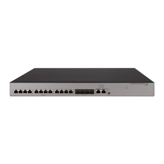
Appendix A Chassis views and technical specifications Chassis views Figure 26 HPE 1950 12XGT 4SFP+ Switch front panel (1) 1/10GBASE-T autosensing Ethernet port LED (2) SFP+ port LED (3) RPS status LED (RPS) (4) System status LED (SYS) (5) Management Ethernet port status LED (MGMT) - Page 33 Input voltage Rated voltage range: 11 VDC to 12 VDC Max voltage range: 10.8 VDC to 13.2 VDC NOTE: Use an HPE RPS800-A RPS as the DC power source. AC: 26 W Power consumption (static) DC: 22 W ...
-
Page 34: Appendix B Ports And Leds
Appendix B Ports and LEDs Ports Console port The switch has two console ports: a serial console port and a mini USB console port. Table 11 Console port specifications Item Serial console port Mini USB console port Connector type RJ-45 Mini USB-Type B Compliant standard EIA/TIA-232... -
Page 35: Sfp+ Port
(nm) (µm) bandwidth distance (MHz × km) HPE X120 1G Category-5 JD089B SFP RJ45 T RJ-45 100 m (328.08 ft) twisted pair Transceiver 550 m (1804.46 ft) Multi-mode, 50/125 HPE X120 1G 500 m (1640.42 ft) - Page 36 Table 16 SFP+ network cables available for the SFP+ ports Product code HPE description Cable length JD095C HPE X240 10G SFP+ SFP+ 0.65m DA Cable 0.65 m (2.13 ft) JD096C HPE X240 10G SFP+ SFP+ 1.2m DA Cable 1.2 m (3.94 ft)
-
Page 37: Leds
(1) Connector (2) Pull latch NOTE: As a best practice, use only HPE SFP/SFP+ transceiver modules and SFP+ network cables for the SFP+ ports. The SFP/SFP+ transceiver modules and SFP+ network cables available for the switch are subject to change over time. For the most up-to-date list of SFP/SFP+ transceiver modules and SFP+ network cables, consult your Hewlett Packard Enterprise sales representative or technical support engineer. -
Page 38: Rps Status Led
LED mark Status Description Flashing yellow (1 Hz) Some ports have failed to pass POST or are faulty. The switch is powered off. RPS status LED The switch supports RPS input. The RPS status LED shows the status of the RPS input. Table 19 RPS status LED description LED mark Status... -
Page 39: Sfp+ Port Led
1/10GBASE-T autosensing Ethernet Description port LED status No link is present on the port. SFP+ port LED Table 22 SFP+ port LED description SFP+ port LED status Description Steady green A link is present on the port and the port is operating at 10 Gbps. Flashing green The port is sending or receiving data at 10 Gbps. -
Page 40: Appendix C Cooling System
The cooling system of the switch includes the air vents and built-in fans in the chassis. For correct operation of this cooling system, consider the site ventilation design when you plan the installation site for the switch. Figure 29 Airflow through the HPE 1950 12XGT 4SFP+ Switch (1) Air inlets (2) Built-in fan air vents... -
Page 41: Document Conventions And Icons
Document conventions and icons Conventions This section describes the conventions used in the documentation. Port numbering in examples The port numbers in this document are for illustration only and might be unavailable on your device. Command conventions Convention Description Boldface Bold text represents commands and keywords that you enter literally as shown. -
Page 42: Network Topology Icons
Network topology icons Convention Description Represents a generic network device, such as a router, switch, or firewall. Represents a routing-capable device, such as a router or Layer 3 switch. Represents a generic switch, such as a Layer 2 or Layer 3 switch, or a router that supports Layer 2 forwarding and other Layer 2 features. -
Page 43: Support And Other Resources
Support and other resources Accessing Hewlett Packard Enterprise Support For live assistance, go to the Contact Hewlett Packard Enterprise Worldwide website: www.hpe.com/assistance To access documentation and support services, go to the Hewlett Packard Enterprise Support Center website: www.hpe.com/support/hpesc Information to collect ... -
Page 44: Websites
For more information and device support details, go to the following website: www.hpe.com/info/insightremotesupport/docs Documentation feedback Hewlett Packard Enterprise is committed to providing documentation that meets your needs. To help us improve the documentation, send any errors, suggestions, or comments to Documentation Feedback (docsfeedback@hpe.com). When submitting your feedback, include the document title,... - Page 45 part number, edition, and publication date located on the front cover of the document. For online help content, include the product name, product version, help edition, and publication date located on the legal notices page.
-
Page 46: Index
Index Numerics IRF member switches in one rack, IRF physical ports, 1/10G BASE-T autosensing Ethernet planning IRF connections, port LED, power cord, 1/10GBASE-T autosensing Ethernet USB mini console cable, port, console 19-inch rack connecting cable, switch installation, connecting USB mini cable, port technical specifications, AC power cord connecting,... - Page 47 site humidity, verifying switch installation, site temperature, workbench switch mounting, examining installation site, humidity (installation site), ID (IRF member), failure (troubleshooting), identifying fiber IRF master switch, laser safety recommendations, IRF member switch physical ports, fixed power module installing failure (troubleshooting), accessories, flow control (parameter), EMI prevention,...
- Page 48 failure (troubleshooting), grounding switch through AC power cord, management Ethernet powering on switch, port, preparing for installation, port LED, preventing master switch EMI prevention, configuring IRF basic settings, procedure IRF fabric, configuring IRF basic settings, member connecting AC power cord, configuring IRF member switch basic settings, connecting DC power cord, connecting grounding cable to chassis,...
- Page 49 grounding the switch with a grounding workbench mounting switch, conductor buried in the earth ground, system administration grounding the switch with grounding strip, troubleshooting configuration terminal problems, installation site cleanliness, installation site dust concentration, troubleshooting fan failure, installation site gas saturation, troubleshooting fixed power module failure, installation site humidity, troubleshooting power module failure,...
- Page 50 first time, HTTP, HTTPS, requirements, workbench mounting switch,...
Need help?
Do you have a question about the OfficeConnect 1950 12XGT 4SFP+ and is the answer not in the manual?
Questions and answers