Table of Contents
Advertisement
Advertisement
Table of Contents

Related Manuals for HPE OfficeConnect 1850 Series


Summary of Contents for HPE OfficeConnect 1850 Series
-
Page 1: Configuration Guide
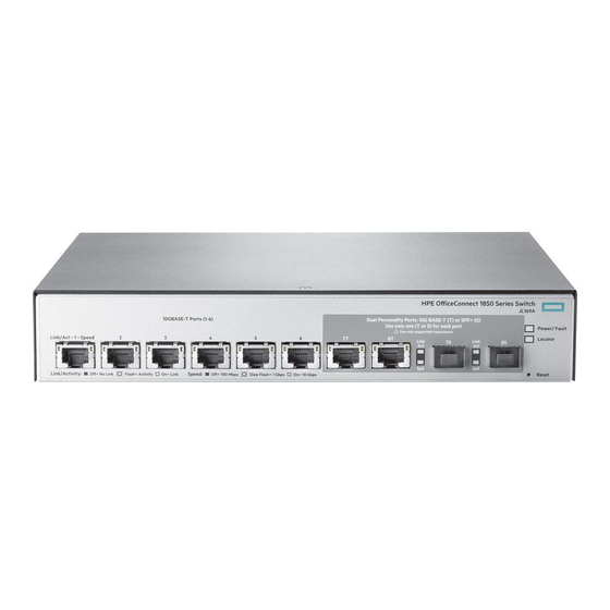
HPE OfficeConnect 1850 6XGT 2XGT/SFP+ Switch Management and Configuration Guide Abstract Use this guide to assist in managing the following HPE OfficeConnect 1850 switch: HPE OfficeConnect 1850 6XGT 2XGT/SFP+ Switch (JL169A) Part Number: 5200-0095 Published: September 2016 Edition: 1... - Page 2 This offer is valid to anyone in receipt of this information and shall expire three years following the date of the final distribu- tion of this product version by Hewlett Packard Enterprise Company. To receive the CD, HPE charges a small fee in order to cover the actual costs of manufacturing and shipping the CD.
-
Page 3: Table Of Contents
Contents Preface......................6 About This Document ........................6 Audience ..........................6 About Your Switch Manual Set ....................... 6 Supported Features ........................7 1 Getting Started ....................8 Connecting the Switch to a Network....................8 Operating System and Browser Support.................. 9 Getting Started With the Web Interface ..................9 Logging On.......................... - Page 4 Spanning Tree Status ......................32 Global STP Settings and Port Status ..................34 Port STP Settings........................36 Auto Recovery Configuration......................39 Loop Protection..........................41 Loop Protection Status......................41 Loop Protection Configuration....................42 Configuring Loop Protection Settings on Interfaces ............43 IGMP Snooping ..........................
- Page 5 EEE Status ........................... 76 10 Diagnostics....................77 Buffered Log ..........................77 Crash Log..........................78 Log Configuration ......................... 79 Cable Diagnostics......................... 81 Ping Test............................83 Reboot Switch..........................84 Factory Defaults..........................84 Support File ..........................85 Locator............................86 MAC Table............................ 87 11 Maintenance Pages ...................89 Password Manager........................
-
Page 6: Preface
About This Document HPE OfficeConnect 1850 series switches provide reliable, plug-and-play Gigabit network connectivity. The HPE OfficeConnect 1850 series switches are ideal for open offices that require silent operation or businesses making the transition from unmanaged to managed networks. The HPE OfficeConnect 1850 series switches can be managed in-band from a remote network station using a web-based graphical user interface (GUI), and its configuration may also be viewed using the SNMP manager. -
Page 7: Supported Features
Supported Features HPE OfficeConnect 1850 series switches include support for the following features: Feature HPE OfficeConnect 1850 Series Switch HTTP and HTTPS sessions 4 each, 8 total SNMP v1/v2c (read-only) community MAC table 16000 entries SNTP server configuration Time zones count... -
Page 8: Getting Started
1 Getting Started This chapter describes how to make the initial connections to the switch and provides an overview of the web interface. Connecting the Switch to a Network To enable remote management of the switch through a web browser, the switch must be connected to the network. -
Page 9: Operating System And Browser Support
Operating System and Browser Support The following operating systems and browsers with JavaScript enabled are supported: Operating System Browser Windows 7 Internet Explorer 9, 10 Firefox 38.2.1, 40.0.3, 41.0.b1 (beta) Chrome 44.0.2403, 45.0.2454, 46.0 (beta) Windows 8/8.1 Internet Explorer 11 (included in base OS 8.1) Firefox 38.2.1, 40.0.3, 41.0.b1 (beta) Chrome 44.0.2403, 45.0.2454, 46.0 (beta) Windows 10... -
Page 10: Interface Layout And Features
Interface Layout and Features Figure 2 shows the initial view. Figure 2. Interface Layout and Features Navigation Pane Graphical Switch Common Links Click on any topic in the navigation pane to display related configuration options. The Dashboard page displays when you first log on and when you click Dashboard in the navigation pane. -
Page 11: Common Page Elements
Common Page Elements Most pages contain a common set of buttons that include one or more of the following: Click on any page to display a help panel that explains the fields and configuration options on the page. Click to send the updated configuration to the switch. -
Page 12: Port Configuration And Summary
Port Configuration and Summary You can point to any port to display the following information about the port: The link status (up or down). Auto negotiation status. Speed and full-duplex/half-duplex settings. The maximum transmission unit (MTU), which is the largest packet size that can be transmitted on the port. -
Page 13: Dashboard
2 Dashboard You can use the Dashboard page to display and configure basic information about the system. The Dashboard page displays basic information such as the configurable switch name and description, the IP address for management access, and the software and operating system versions. This page also shows resource usage statistics. - Page 14 Table 1. Dashboard Page Fields Field Description System Information A description of the switch hardware, including the hardware type, software version, operating system version, and boot loader (U-Boot) version. System Description Enter the preferred name to identify this switch. A maximum of 64 alpha-numeric characters including hyphens, commas and spaces are allowed.
-
Page 15: Setup Network
3 Setup Network You can use the Setup Network pages to configure how a management computer connects to the switch and how the switch connects to a server to synchronize its time. Get Connected Use the Get Connected page to configure settings for the network interface. The network interface is defined by an IP address, subnet mask, and gateway. - Page 16 Table 2. Get Connected Fields Field Description Network Details Protocol Type Select the type of network connection: Static—Select this option to enable the IP address, subnet mask, and gateway fields for data entry. DHCP—Select this option to enable the switch to obtain IP information from a DHCP server on the network.
- Page 17 Field Description Management Port Access to the management software can also be controlled by the selection of a management port. The selected management port is auto-configured to be an untagged member of the management VLAN and is excluded from any other untagged VLANs. When the switch boots with the default configuration, any port can be used as management port and this field is configured as None.
-
Page 18: System Time
System Time Pages You click Setup Network > System Time to display the web pages for configuring the system clock, SNTP client functionality, system time zone, and daylight saving time settings. System Time The System Time page displays the current time, time zone, and Daylight Saving Time settings, and enables you to configure the time display format. -
Page 19: Time Configuration
Field Description Time Zone Time Zone The currently set time zone. The default is (GMT) Greenwich Mean Time: Dublin, Edinburgh, Lisbon, London. Acronym The acronym for the time zone, if one is configured on the system (e.g., PST, EDT). Daylight Saving Time Daylight Saving Time Shows whether Daylight Saving Time (DST) is enabled and the mode of operation: ... - Page 20 Figure 7. Time Configuration Page Table 4. Time Configuration Fields Field Description Set System Time Select Using Simple Network Time Protocol (SNTP) to configure the switch to acquire its time settings from an SNTP server. When selected, only the SNTP Configuration fields are available for configuration.
- Page 21 Field Description Last Update Status The status of the last update request to the SNTP server, which can be one of the following values: Other—None of the following values apply or no message has been received. Success—The SNTP operation was successful and the system time was updated. ...
-
Page 22: Time Zone Configuration
Time Zone Configuration The Time Zone Configuration page is used to configure your local time zone. To display this page, click Setup Network > System Time in the navigation pane and click the Time Zone tab. Figure 8. Time Zone Configuration Page Table 5. -
Page 23: Daylight Saving Time Configuration
Daylight Saving Time Configuration The Daylight Saving Time Configuration page is used to configure if and when Daylight Saving Time (DST) occurs within your time zone. When configured, the system time adjusts automatically one hour forward at the start of the DST period, and one hour backward at the end. To display the Daylight Saving Time page, click Setup Network >... - Page 24 Table 6. Daylight Saving Time Configuration Fields Field Description Daylight Saving Time Select how DST will operate: Disable—No clock adjustment will be made for DST. This is the default selection. Recurring—The settings will be in effect for the upcoming period and subsequent years. ...
-
Page 25: Switching Features
4 Switching Features You can use the Switching pages to configure port operation and capabilities. Port Configuration You can use the Port Configuration pages to display port status, configure port settings, and view sta- tistics on packets transmitted on the port. Port Status The Port Status page displays the operational and administrative status of each port and enables port configuration. -
Page 26: Modifying Interface Settings
Field Description Physical Type The interface type, which can be one of the following: Normal—The port is a normal port, which means it is not a Link Aggregation Group (LAG) member or configured for port mirroring. All ports are normal ports by default. ... -
Page 27: Port Summary Statistics
Table 8. Edit Port Configuration Fields Field Description Interface The interface or interfaces to be configured. Admin Mode Select Enabled to make the port accessible on the network, or Disabled to prevent the port from receiving or forwarding packets. Physical Mode Select the duplex mode and transmission rate for the selected interface. -
Page 28: Port Mirroring
Table 9. Port Summary Statistics Fields Field Description Interface The port or trunk ID. Received Packets w/o Error The count of packets received on the port without any packet errors. Received Packets with Error The count of packets received on the port with errors. Broadcast Received Packets The count of broadcast packets received on the port. - Page 29 Figure 13. Port Mirroring Page Table 10. Port Mirroring Fields Field Description Port Mirroring Enables or disables port mirroring globally on the switch. This feature is disabled by default. Destination Port Select the switch port to which packets will be mirrored. Typically, a network protocol analyzer is connected to this port.
-
Page 30: Jumbo Frames
Table 11. Add Port Mirroring Source Fields Field Description Available Source Port(s) Select the source ports or trunks to mirror to the destination port. To select multiple source ports, hold down Ctrl while selecting ports. You can also select the CPU to mirror traffic sent from the switch CPU to the switch interfaces or vice versa. -
Page 31: Flow Control
HPE OfficeConnect 1850 series switches support STP versions IEEE 802.1D (STP), and 802.1w (Rapid STP, or RSTP). RSTP reduces the convergence time for network topology changes to about 3 to 5 seconds from the 30 seconds or more for the IEEE 802.1D STP standard. -
Page 32: Spanning Tree Status
Spanning Tree Status To display the Spanning Tree Status page, click Switching > Spanning Tree in the navigation pane, and make sure the Status tab is selected. This page includes information about global STP settings and interface status information. Figure 17. Spanning Tree Status Page Page 32 Spanning Tree... - Page 33 The following fields show global and per-interface STP settings: Table 12. Spanning Tree Status Fields Field Description Spanning Tree Bridge Status Spanning Tree Identifies whether STP is enabled or disabled on the switch. Protocol Version Select the protocol version in use: ...
-
Page 34: Global Stp Settings And Port Status
Field Description State Ports can be in one of the following STP states, depending on its configuration and the status of the STP topology convergence: Blocking—The port discards user traffic and receives, but does not send, BPDUs. During the election process, all ports are in the blocking state. The port is blocked to pre- vent network loops. - Page 35 The following fields configure global STP settings: Table 13. Spanning Tree Bridge Configuration Fields Field Description Spanning Tree Bridge Configuration Spanning Tree Click Enabled to enable the Spanning Tree protocol mode on all ports. This feature is disabled on all ports by default. Protocol Version Select the protocol version to use: ...
-
Page 36: Port Stp Settings
Field Description Spanning Tree Interface Status Table Interface The port or trunk associated with the rest of the data in the row. Port Role The role of the port with respect to spanning tree functionality, which is one of the following: ... - Page 37 Figure 19. Edit Spanning Tree Port Configuration Page The Edit Spanning Tree Port Configuration page enables you to configure settings and view status and statistics for the selected interfaces. Table 14. Edit Spanning Tree Port Configuration Fields Field Description Configurable Port Settings Interface The port and trunk IDs selected for configuration.
- Page 38 Field Description Port Path Cost Specify the path cost, which is used when establishing the active topology of the network. Lower path cost ports are chosen as forwarding ports in favor of higher path cost ports. Specify Auto or assign a value from 1 to 200000000, or specify 0 for Auto mode. When set to 0, the path cost is set using the 802.1D recommended values.
-
Page 39: Auto Recovery Configuration
Auto Recovery Configuration The switch supports Auto Recovery for BPDU Guard and BPDU Rate Limiting. A switch port will be placed into a diagnostically disabled state when defined error conditions are met. The error conditions that cause a port to be placed into the diagnostically disabled state are as follows: ... - Page 40 Table 15. Auto Recovery Configuration Fields Field Description Auto Recovery Components BPDU Guard When BPDU Guard Auto Recovery is enabled, the port will be enabled once the configured Recovery Time expires. If the port receives another BPDU, it will be disabled again. If the BPDU Guard Auto Recovery mode is disabled, a port that has received a BPDU and has been placed in the diagnostically disabled state will remain in that state until an administrator manually enables it.
-
Page 41: Loop Protection
Loop Protection Loops on a network consume resources and can degrade network performance. Detecting loops man- ually can be very cumbersome and time consuming. The HPE OfficeConnect 1850 series switch soft- ware provides an automatic loop protection feature. When loop protection is enabled on the switch and on one or more interfaces (ports or trunks), the interfaces send loop protection protocol data units (PDUs) to the multicast destination address 09:00:09:09:13:A6. -
Page 42: Loop Protection Configuration
Table 16. Loop Protection Status Fields Field Description Interface The port or trunk ID. Loop Protection Indicates whether the feature is administratively enabled or disabled on the port. Loop Protection is disabled by default. Configured Action Taken The action that is set to occur when a loop is detected on the port with loop protection enabled: ... -
Page 43: Configuring Loop Protection Settings On Interfaces
Table 17. Loop Protection Configuration Global Fields Field Description Loop Protection Select Enabled or Disabled to administratively enable or disable this feature globally on the switch. This feature is disabled by default. Transmission Time The interval at which the switch sends loop protection PDUs on interfaces that are enabled to send them. - Page 44 Table 18. Loop Protection Configuration Global Fields Field Description Interface The port or ports that are being configured. Loop Protection Select Enabled or Disabled to administratively enable or disable this feature on the selected interfaces. By default, this feature is disabled on all interfaces. Note that loop protection can be enabled on static trunks, but cannot be enabled on trunks that are dynamically formed through LACP.
-
Page 45: Igmp Snooping
IGMP Snooping Internet Group Management Protocol (IGMP) snooping allows a device to forward multicast traffic intelligently. Multicast IP traffic is traffic that is destined to a host group. Host groups are identified by class D IP addresses, which range from 224.0.0.0 to 239.255.255.255. Based on the IGMP query and report messages, the switch forwards traffic only to the ports that request the multicast traffic. -
Page 46: Virtual Lan
VLAN ID. A given port may handle traffic for more than one VLAN, but it can only sup- port one default VLAN ID. HPE OfficeConnect 1850 series switches support up to 64 VLANs. Viewing VLAN Status and Adding VLANs Use the VLAN Status page to view information on VLANs currently defined on the switch and to add and edit VLAN information. -
Page 47: Adding Vlans
The following information displays for each VLAN: Table 20. VLAN Configuration Fields Field Description VLAN ID The numerical VLAN identifier (VID) assigned to the VLAN, from 1 to 4093. Note: VLAN 0 (VID = 0x000 in a frame) is reserved and is used to indicate that the frame does not belong to any VLAN. -
Page 48: Changing A Vlan Name
Changing a VLAN Name When you create a VLAN, a default name is automatically assigned in the form VLANnnnn, where nnnn is the VLAN number with preceding zeros as needed. To change the VLAN name, select it on the VLAN Status page and click Edit. Figure 27. - Page 49 Table 21. VLAN Port Membership Fields Field Description VLAN ID Select the VLAN ID for which you want to view interface memberships. Interface The port or trunk ID. Participation/Tagging The current membership mode and tagging behavior for each port in this VLAN, which is one of the following: ...
-
Page 50: Vlan Port Configuration
VLAN Port Configuration Use the VLAN Port Configuration page to view the port VLAN IDs (PVIDs) and priority values assigned to each VLAN. To view this page, click VLANs > VLAN Port Configuration in the navigation pane. Figure 29. VLAN Port Configuration Page Table 22. -
Page 51: Trunks
6 Trunks Trunks allow for the aggregation of multiple full-duplex Ethernet links into a single logical link. Network devices treat the aggregation as if it were a single link, which increases fault tolerance and provides load sharing capability. A trunk interface can be either static or dynamic: ... -
Page 52: Trunk Configuration
Trunk Configuration You can use the Trunk Configuration page to view and edit trunks. The number of trunks on the system is fixed, and all trunks are disabled by default. You can enable, disable, and edit settings for each trunk. Click Trunk > Trunk Configuration in the navigation pane. Figure 30. -
Page 53: Modifying Trunk Settings
Modifying Trunk Settings To modify a trunk, select it and click Edit. The Edit Existing Trunk page displays: Figure 31. Edit Existing Trunk Page You can define the trunk name, administratively enable and disable the trunk, and select between static and dynamic mode, as described in Table 23 on page 52. -
Page 54: Trunk Statistics
Note the following considerations when configuring trunks and trunk members: All ports in a trunk must have the same full-duplex speed. Loop protection is supported on static trunks, but not on dynamic trunks. If loop protection is enabled on a static trunk that is now being changed to a dynamic trunk, loop protection will be dis- abled on the trunk. -
Page 55: Link Layer Discovery Protocol (Lldp And Lldp-Med)
7 Link Layer Discovery Protocol (LLDP and LLDP-MED) LLDP is a standardized discovery protocol defined by IEEE 802.1AB. It allows stations residing on a LAN to advertise major capabilities, physical descriptions, and management information to other devices on the network. A network management system (NMS) can access and display this informa- tion. - Page 56 You can configure the following global settings: Table 26. LLDP Global Configuration Fields Field Description Transmit Interval Specify the time between transmission of LLDPDUs. The range is from 5 to 32768 seconds and the default is 30 seconds. Transmit Hold Multiplier Specify the multiplier value on the transmit interval, which is used to compute the time-to-live (TTL) value associated with LLDPDUs.
-
Page 57: Lldp Local Device Summary
Figure 34. Edit LLDP Interface Select a box to enable the associated feature. Clear a box to disabled the associated feature. To modify settings on all interfaces, click Edit All. LLDP Local Device Summary Use the LLDP Local Device Summary page to view LLDP information for switch interfaces. To display this page, click LLDP >... -
Page 58: Displaying Port Details
Table 28. LLDP Local Device Summary Fields Field Description Local Device Summary Chassis ID The hardware platform identifier for the device. Chassis ID Subtype The type of information used to identify the chassis. Capabilities Supported The primary function(s) the device supports. Capabilities Enabled The primary function(s) the device supports that are enabled. -
Page 59: Lldp Remote Device Summary
In addition to the fields described in Table 28 on page 58, this page displays the following fields. Table 29. LLDP Local Device Information Fields Field Description System Name The user-configured system name for the device. The system name is configured on the Dashboard page. -
Page 60: Lldp Global Statistics
Table 30. LLDP Remote Device Summary Fields Field Description Interface The HPE OfficeConnect 1850 interface that received the LLDP data from the remote system. Remote ID The identifier assigned to the remote system that sent the LLDPDU. Chassis ID The hardware platform ID for the remote system. - Page 61 Table 31. LLDP Global Statistics Fields Field Description Global Statistics Insertions The number of times the complete set of information advertised by a particular MAC Service Access Point (MSAP) has been inserted into tables associated with the remote systems. Deletions The number of times the complete set of information advertised by a particular MSAP has been deleted from tables associated with the remote systems.
-
Page 62: Lldp-Med Global Configuration
LLDP-MED is enabled. The default is 3. Device Class The device's MED classification. The HPE OfficeConnect 1850 switch is classified as a Network Connectivity device. If you change the Fast Start Repeat Count, click Apply to save any changes for the current boot ses- sion. - Page 63 The switch waits for the LLDP-MED device to advertise its information before the switch transmits its own LLDP-MED TLVs, at which point the operational status becomes enabled. Transmitted TLVs The LLDP-MED TLV(s) that the interface transmits. The HPE OfficeConnect 1850 switch, can transmit TLVs of the following types: Capabilities ...
-
Page 64: Lldp-Med Local Device Summary
LLDP-MED Local Device Summary Use the LLDP-MED Local Device Summary to view the information that is advertised by the switch interfaces when they are enabled for LLDP-MED. To display this page, click LLDP-MED > Local Devices in the navigation pane. Figure 41. -
Page 65: Lldp-Med Remote Device Summary
LLDP-MED Remote Device Summary Use the LLDP-MED Remote Device Summary page to view information about the remote devices the local system has learned through the LLDP-MED data units received on its interfaces. Information is available about remote devices only if an interface receives an LLDP-MED data unit from a device. To display this page, click LLDP-MED >... -
Page 66: Displaying Remote Device Details
Displaying Remote Device Details To view additional information about a remote device, select the interface that received the LLDP-MED data and click Details. Figure 43. LLDP-MED Remote Device Information Page The following additional fields appear on the LLDP-MED Remote Device Information page: Field Description Capability Information... - Page 67 Field Description Network Policy Information This section describes the information in the network policy TLVs received in the LLDP-MED frames on this interface. Media Application Type The media application type received in the TLV from the remote device. The application types are unknown, voicesignaling, guestvoice, guestvoicesignalling, softphonevoice, videoconferencing, streammingvideo, vidoesignalling.
-
Page 68: Security
8 Security The HPE OfficeConnect 1850 series switch software includes a robust set of built-in denial-of-service (DoS) and storm-control protections, and allows configuring secure HTTP (HTTPS) management ses- sions. Advanced Security Configuration The HPE OfficeConnect 1850 series switch software provides an Auto Denial-of-Service (DoS) protec- tion feature to help protect against DoS attacks. -
Page 69: Secure Connection
Save Configuration. Secure Connection The HPE OfficeConnect 1850 series switch software allows the administrator to enable or disable Secure HTTP protocol (HTTPS). When enabled, the administrator can establish a secure connection with the switch using the Secure Sockets Layer (SSL) protocol. - Page 70 The browser and server use this information to negotiate a secure connection in the following manner: The browser verifies the certificate authority’s authenticity by checking it against its own list of CAs. (web browsers such as Microsoft Internet Explorer and Mozilla Firefox maintain data on trusted CAs.) ...
-
Page 71: Uploading Ssl Certificates And Encryption Files
Field Description HTTPS Session Hard Time The number of minutes after which an HTTPS session times-out, regardless of recent user activity. The default value is 24 hours. Certificate Status The status of the SSL certificate generation process: Present—A certificate is available for use with HTTPS sessions. Absent—No certificate is available on the switch. - Page 72 Figure 46. Upload Certificates Select one of the following from the File Type field: SSL Trusted Root Certificate PEM File A PEM-encoded SSL certificate that has been digi- — tally signed by a certificate authority. SSL Server Certificate PEM File A PEM-encoded SSL certificate that has been signed by —...
-
Page 73: Storm Control Configuration
Storm Control Configuration The Storm Control feature protects against conditions where incoming packets flood the LAN, causing network performance degradation. The software includes Storm Control protection for unicast traffic with an unknown destination, and for broadcast and multicast traffic. When enabled, the storm control threshold is automatically set to 5% of port speed. - Page 74 Table 38. Storm Control Configuration Fields Field Description Storm Control Features Storm Control Storm control enables the rate-limiting of incoming unicast (with unknown destination), multicast, and broadcast traffic to prevent unnecessary congestion in the network. When enabled, the storm control threshold is automatically set to 5% of port speed. If the incoming rate of unicast (with unknown destination), multicast, or broadcast packets exceeds this value, the port moves to the diagnostically disabled state and remains in that state until it is re-enabled by the Auto recovery feature.
-
Page 75: Green Features
9 Green Features The green features on the switch are Efficient Ethernet (EEE) technologies, as defined by the IEEE 802.3az task force. These features are designed to reduce per-port power usage by shutting down ports when no link is present or when activity is low. Green Features Configuration To display the Green Features configuration page, click Green Features >... -
Page 76: Eee Status
EEE Status When EEE is enabled, you can use the EEE status page to view estimated power savings and power consumption information. This page also displays status information for each interface. To display the EEE status page, click Green Features > EEE Status in the navigation pane. Figure 49. -
Page 77: 10 Diagnostics
10 Diagnostics You can use the Diagnostics pages to test, reboot, and view log and configuration information on the HPE OfficeConnect 1850 series switch. Buffered Log The log messages that the switch generates in response to events, faults, errors, and configuration changes are stored locally on the switch in the RAM (cache). -
Page 78: Crash Log
The following information displays in the Buffered Log table. Table 41. Buffered Log Fields Field Description Log Index The log number. Log Time Time at which the log was entered in the table. Severity The severity level associated with the log message. The severity can be one of the following: ... -
Page 79: Log Configuration
Log Configuration The HPE OfficeConnect 1850 series switch software supports logging system messages to the buff- ered log file or forwarding messages over the network using the Syslog protocol. Syslog messages can be captured by a designated host on the network that is running a Syslog daemon. You can use the Log Configuration page to configure buffered log and Syslog settings. - Page 80 Figure 52. Log Configuration Page Table 42. Log Configuration Fields Field Description Buffered Log Configuration Buffered Logging Enables or disables logging system events to the buffered log. This feature is enabled by default. Severity Filter Specify type of system messages logged using the Buffered Logging Level setting: ...
-
Page 81: Cable Diagnostics
Cable Diagnostics Use the Cable Diagnostics page to test the cable connected to a port on the device. The cable diag- nostics uses Time Domain Reflectometry (TDR) technology to test the quality and characteristics of a copper cable attached to a port. Cables up to 120 meters long can be tested. CAUTION: The link is forced down for the selected interface during the cable test period. - Page 82 Field Description Failure Location Distance The estimated distance from the end of the cable to the failure location. Note: This field displays a value only when the cable status is Open or Short; otherwise, this field is blank. To perform cable diagnostics, select one or more ports and click Test. The cable diagnostics may take up to 10 seconds to complete.
-
Page 83: Ping Test
Ping Test Use the Ping page to send one or more ping requests from the switch to a specified IP address. You can use the ping request to check whether the switch can communicate with a particular host on an IP network. -
Page 84: Reboot Switch
Reboot Switch Use this feature to perform a software reboot of the switch. If you applied configuration changes, click the Save Configuration button in the upper right of any page before rebooting. If the switch is config- ured to use DHCP to acquire its IP address, the address may change upon restart; you will need to determine the address before logging back in to the management utility. -
Page 85: Support File
Support File Use the support file page to display summary information for the switch on a single page. To display the Support File page, click Diagnostics > Support File in the navigation pane. Figure 57 shows a partial view of the page. Figure 57. -
Page 86: Locator
Port Status and Port Summary Statistics—Port and trunk configuration details, summary, and sta- tistics Trunk Configuration and Trunk Statistics—Trunk configuration details and flap count statistics Jumbo Frames Configuration—Enable/disable status Flow Control and Storm Control Configuration—Enable/disable status ... -
Page 87: Mac Table
MAC Table The MAC address table keeps track of the Media Access Control (MAC) addresses associated with each port. This table enables the switch to forward unicast traffic through the appropriate port. The MAC address table is sometimes called the bridge table or the forwarding database. IMPORTANT: The address table supports up to 16K MAC address entires;... - Page 88 Table 45. MAC Table Fields Field Description Maximum Entries Supported The maximum number of MAC address entries that can be learned on the switch. VLAN ID The VLAN or VLANs with which the MAC address is associated. MAC Address A unicast MAC address for which the switch has forwarding and/or filtering information. The format is a six-byte MAC address, with each byte separated by colons.
-
Page 89: Maintenance
11 Maintenance Pages You can use the maintenance pages to change the password for logging in to the configuration utility, back up and update the switch software, and select which of two software images is the active image and which is the backup image. Password Manager Use the Password Manager page to change the password used to access the web interface. -
Page 90: Backup And Update Manager
Backup and Update Manager The File Transfer page enables you to save a backup copy of the switch’s firmware image or configura- tion file on a local system or network directory and to update files on the switch by transferring newer files from a remote system. -
Page 91: Updating Files
Configure the following settings: Table 47. TFTP and HTTP Backup File Fields Field Description File Type Select the type of file to back up from the switch to a remote system. You can back up the active or backup image, the system configuration file, the error log in persistent memory (also referred to as the event log), and the buffered log in RAM. - Page 92 Table 48. HTTP Update File Fields Field Description File Type Select the type of file to update: Backup Code—Select this option to transfer a new image to the switch. The code file is stored as the backup image. After updating the backup image, you can use the Dual Image Configuration page to make it the active image upon the next reboot.
-
Page 93: Dual Image Configuration
Dual Image Configuration The switch can store up to two software images. One image is the active image and the other is the backup image (not actively running on the switch). You can select which image to load during the next boot cycle and add a description for each image on the device. -
Page 94: A Support And Other Resources
Hewlett Packard Enterprise Support Center More Information on Access to Support Materials page: www.hpe.com/support/AccessToSupportMaterials NOTE:IMPORTANT: Access to some updates might require product entitlement when accessed through the Hewlett Packard Enterprise Support Center. You must have an HPE Passport set up with relevant entitlements. Page 94 Support and other resources... -
Page 95: Websites
Websites Website Link www.hpe.com/info/enterprise/docs Hewlett Packard Enterprise Information Library Hewlett Packard Enterprise Support Center www.hpe.com/support/hpesc Contact Hewlett Packard Enterprise Worldwide www.hpe.com/assistance Subscription Service/Support Alerts www.hpe.com/support/e-updates Software Depot www.hpe.com/support/softwaredepot Customer Self Repair www.hpe.com/support/selfrepair Insight Remote Support www.hpe.com/info/insightremotesupport/docs Serviceguard Solutions for HP-UX www.hpe.com/info/hpux-serviceguard-docs... -
Page 96: Documentation Feedback
Documentation Feedback ). When submitting your feedback, include the document title, part number, edi- docsfeedback@hpe.com tion, and publication date located on the front cover of the document. For online help content, include the product name, product version, help edition, and publication date located on the legal notices page. -
Page 97: B Warranty Information
For important safety, environmental, and regulatory information, see Safety and Compliance Information for Server, Storage, Power, Networking, and Rack Products, available at www.hpe.com/support/Safety-Compliance-EnterpriseProducts. Warranty information HPE ProLiant and x86 Servers and Options ( http://www.hpe.com/support/ProLiantServers-Warranties HPE Enterprise Servers ( http://www.hpe.com/support/EnterpriseServers-Warranties HPE Storage Products ( http://www.hpe.com/support/Storage-Warranties...
Need help?
Do you have a question about the OfficeConnect 1850 Series and is the answer not in the manual?
Questions and answers