
Related Manuals for HPE OfficeConnect 1950 Series


Summary of Contents for HPE OfficeConnect 1950 Series
- Page 1 HPE OfficeConnect 1950 Switch Series Getting Started Guide Part number: 5998-8110 Document version: 6W103-20160825...
- Page 2 © Copyright 2015-2016 Hewlett Packard Enterprise Development LP The information contained herein is subject to change without notice. The only warranties for Hewlett Packard Enterprise products and services are set forth in the express warranty statements accompanying such products and services. Nothing herein should be construed as constituting an additional warranty. Hewlett Packard Enterprise shall not be liable for technical or editorial errors or omissions contained herein.
-
Page 3: Table Of Contents
Connecting the mini USB console cable ·································································································· 20 Setting terminal parameters ····················································································································· 21 Powering on the switch ···························································································································· 22 Setting up an HPE OfficeConnect 1950 stack ·············································· 23 Setup flow ························································································································································ 23 Planning the stack setup ·································································································································· 24 ... - Page 4 HPE 1950 24G 2SFP+ 2XGT ·················································································································· 32 HPE 1950 48G 2SFP+ 2XGT ·················································································································· 32 HPE 1950 24G 2SFP+ 2XGT PoE+(370W) ····························································································· 33 HPE 1950 48G 2SFP+ 2XGT PoE+(370W) ····························································································· 34 HPE 1950 12XGT 4SFP+ ························································································································ 34 ...
-
Page 5: Preparing For Installation
To avoid ESD damage, wear an ESD wrist strap when hot-swapping a power supply. Examining the installation site The HPE OfficeConnect 1950 switches must be used indoors. You can mount your switch in a rack or on a workbench, but make sure the following conditions exist: •... -
Page 6: Temperature/Humidity
• The rack or workbench has a good ventilation system. • The rack is sturdy enough to support the switch and its accessories. • The rack or workbench is reliably grounded. To ensure correct operation and a long service life of your switch, install it in an environment that meets the requirements described in the following subsections. -
Page 7: Laser Safety
Do not stare into any fiber port when the switch has power. The laser light emitted from the optical fiber might hurt your eyes. The HPE OfficeConnect 1950 switches are Class 1 laser devices. Installation tools The following installation tools are user supplied: •... - Page 8 Quantity Applicable models code M6 screw and floating nut (user supplied) All HPE 1950 switches Grounding cable (provided) • HPE 1950 24G 2SFP+ 2XGT • HPE 1950 48G 2SFP+ 2XGT 5185-9292 • HPE 1950 12XGT 4SFP+ Grounding cable (provided) •...
-
Page 9: Installing The Switch
Installing the switch CAUTION: Keep the tamperproof seal on a mounting screw on the chassis cover intact. If you want to open the chassis, contact Hewlett Packard Enterprise for permission. Otherwise, Hewlett Packard Enterprise shall not be liable for any consequences. Figure 1 Hardware installation flow Start Install the switch... -
Page 10: Installing The Switch In A 19-Inch Rack
(2 ) Screw hole for attaching the bracket to the rack post Attaching the mounting brackets to the switch The HPE 1950 12XGT 4SFP+, HPE 1950 24G 2SFP+ 2XGT, and HPE 1950 48G 2SFP+ 2XGT switches provide one front mounting position (near the network ports) and one rear mounting... - Page 11 Repeat step to attach the other mounting bracket to the chassis. Figure 4 Attaching a two-hole mounting bracket to the front mounting position on an HPE 1950 24G 2SFP+ 2XGT switch Figure 5 Attaching a two-hole mounting bracket to the rear mounting position on an HPE...
-
Page 12: Rack-Mounting The Switch
Figure 7 Attaching a four-hole mounting bracket to the rear mounting position on an HPE 1950 24G 2SFP+ 2XGT PoE+(370W) switch Figure 8 Attaching a four-hole mounting bracket to the mid-mounting position on an HPE 1950 24G 2SFP+ 2XGT PoE+(370W) switch Rack-mounting the switch This task requires two people. -
Page 13: Mounting The Switch On A Workbench
Figure 10 Mounting an HPE 1950 24G 2SFP+ 2XGT PoE+(370W) switch by the rear mounting position Figure 11 Mounting an HPE 1950 24G 2SFP+ 2XGT PoE+(370W) switch by the mid-mounting position Mounting the switch on a workbench IMPORTANT: • Ensure 10 cm (3.9 in) of clearance around the chassis for heat dissipation. -
Page 14: Grounding The Switch
Figure 12 Mounting the switch on a workbench Grounding the switch WARNING! Correctly connecting the switch grounding cable is crucial to lightning protection and EMI protection. The power input end of the switch has a noise filter, whose central ground is directly connected to the chassis to form the chassis ground (commonly known as PGND). -
Page 15: Grounding The Switch With A Grounding Conductor Buried In The Earth Ground
Figure 13 Connecting the grounding cable to the grounding hole of the switch (1) Chassis rear panel (2) Grounding sign (3) Grounding hole (4) Ring terminal (5) Grounding cable (6) Grounding screw Connect the other end of the grounding cable to the grounding strip. a. -
Page 16: Connecting The Power Cord
HPE A-RPS800 Connecting the switch to an A-RPS800 As a best practice, use HPE RPS and cables for RPS power input. Connecting the switch to an AC power source Connect the AC power cord plug to the AC-input power receptacle on the switch. -
Page 17: Connecting The Switch To An A-Rps1600
Figure 16 Passing the cable tie through the cable retainer Figure 17 Using the cable tie to secure the AC power cord Connecting the switch to an A-RPS1600 Orient the plug with the power receptacle on the power supply, and insert the plug into the receptacle (See callout 1 in Figure 18). -
Page 18: Connecting The Switch To An A-Rps800
Figure 18 Connecting the A-RPS1600 power cord to an HPE 1950 24G 2SFP+ 2XGT PoE+(370W) switch Connecting the switch to an A-RPS800 Remove the cover over the DC-input receptacle on the switch as shown in Figure Reinstall the cover if you are not to connect a power cord to the receptacle. -
Page 19: Verifying The Installation
Figure 20 Connecting the A-RPS800 power cord to an HPE 1950 12XGT 4SFP+ switch Verifying the installation After you complete the installation, verify the following items: • There is enough space for heat dissipation around the switch. • The rack or workbench is stable. -
Page 20: Accessing The Switch For The First Time
Accessing the switch for the first time You can use one of the following default methods to access the switch: • Logging in to the Web interface—For detailed device configuration. • Logging in to the quick set-up CLI—For quick set-up of key device configuration. Logging in to the Web interface Log in to the Web interface through HTTP or HTTPS. -
Page 21: Logging In To The Web Interface For The First Time
Item Setting Password None User role network-admin NOTE: If the network has a DHCP server, you must use the DHCP assigned IP address to access the device. For more information, see "Logging in to the Web interface for the first time."... -
Page 22: Logging In To The Quick Set-Up Cli
Setting up the configuration environment The HPE 1950 12XGT 4SFP+ switch has a serial console port and a mini USB console port. You can access the switch through the serial console port or the mini USB console port. As a best practice, use the serial console port to access the HPE 1950 12XGT 4SFP+ switch. -
Page 23: Connecting The Console Cable
Figure 21 Connecting the serial console port to a PC Connecting the console cable A console cable is an 8-core shielded cable. It has a crimped RJ-45 connector at one end for connecting to the console port of the switch, and a DB-9 female connector at the other end for connecting to the serial port on the configuration terminal. -
Page 24: Connecting The Mini Usb Console Cable
Connect the RJ-45 connector to the console port of the switch. NOTE: The serial ports on PCs do not support hot swapping. To connect a PC to an operating switch, first connect the PC end. To disconnect a PC from an operating switch, first disconnect the switch end. Connecting the mini USB console cable A mini USB console cable has a mini USB-Type B connector at one end to connect to the mini USB console port on the switch, and a standard USB Type A connector at the other end to connect to the... -
Page 25: Setting Terminal Parameters
Figure 24 Software Installation Click Finish. Figure 25 Completing the device driver installation wizard Setting terminal parameters To access the switch through the console port, you must run a terminal emulator program, TeraTermPro or PuTTY, on the configuration terminal. For information about using a terminal emulator program, see the program's user guide. -
Page 26: Powering On The Switch
The following are the required terminal settings: • Bits per second—38400. • Data bits—8. • Stop bits—1. • Parity—None. • Flow control—None. Powering on the switch Before powering on the switch, verify that the following requirements are met: • The power cord is correctly connected. •... -
Page 27: Setting Up An Hpe Officeconnect 1950 Stack
NOTE: • Stacking and stack are called IRF on the webpages and in online help. • The HPE 1950 12XGT 4SFP+ switch can form a stack only with switches of the same type. Setup flow Figure 26 Stack setup flow... -
Page 28: Planning The Stack Setup
The switching capacity of a stack equals the total switching capacities of all member switches. An HPE OfficeConnect 1950 stack can have a maximum of four switches. Plan the installation site depending on your network solution, as follows: •... -
Page 29: Planning Stack Topology And Connections
Make sure the physical interfaces bound to a stack IRF port are the same type. The HPE OfficeConnect 1950 switches support 10-GE stack connections through 1/10-GE Ethernet ports or SFP+ ports. You can bind multiple 1/10-GE Ethernet ports or SFP+ ports to an IRF port for increased bandwidth and availability. -
Page 30: Identifying Stack Physical Interfaces On The Member Switches
HPE 1950 48G 2SFP+ 2XGT Two fixed SFP+ ports and two fixed 1/10GBASE-T • autosensing Ethernet ports on the front panel HPE 1950 24G 2SFP+ 2XGT PoE+(370W) • HPE 1950 48G 2SFP+ 2XGT PoE+(370W) Four fixed SFP+ ports and 12 fixed 1/10GBASE-T •... - Page 31 Figure 29 Connecting the switches in one rack (1) Figure 30 Connecting the switches in one rack (2) Figure 31 Stack topology Connecting the stack member switches in a ToR solution You can install stack member switches in different racks side by side to deploy a top of rack (ToR) solution.
-
Page 32: Configuring Basic Stack Settings
• Wear an ESD wrist strap when you connect twisted pair cables, SFP+ network cables, or SFP+ transceiver modules and fibers. For how to connect them, see HPE SFP/SFP+/XFP/SFP28 Transceiver Modules and Cables Installation Guide. -
Page 33: Maintenance And Troubleshooting
Maintenance and troubleshooting Power supply failure The HPE 1950 24G 2SFP+ 2XGT and HPE 1950 48G 2SFP+ 2XGT switches use built-in power supplies and support only AC power input. The HPE 1950 12XGT 4SFP+, HPE 1950 24G 2SFP+ 2XGT PoE+(370W), and HPE 1950 48G 2SFP+ 2XGT PoE+(370W) switches use built-in power supplies and support AC power input, RPS power input, and concurrent AC and RPS DC inputs. -
Page 34: Concurrent Rps And Ac Input Failure
Solution To resolve the problem: Verify that the switch is securely connected to the RPS. Verify that the RPS is operating correctly. Verify that the operating temperature of the switch is in the acceptable range, and the power supply has good ventilation. Over-temperature can cause the power supply to stop working and enter the protection state. -
Page 35: Configuration Terminal Display Problems
Configuration terminal display problems No display Symptom The configuration terminal does not display any information when the switch is powered on. Solution To resolve the problem: Verify that the power system is operating correctly. Verify that the switch is operating correctly. Verify that the console cable has been connected correctly. -
Page 36: Appendix A Chassis Views And Technical Specifications
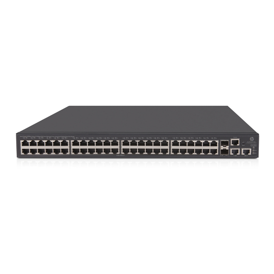
Appendix A Chassis views and technical specifications Chassis views HPE 1950 24G 2SFP+ 2XGT Figure 33 Front panel (1) 10/100/1000Base-T auto-sensing Ethernet port (2) SFP+ port (3) 1/10GBase-T auto-sensing Ethernet port (4) Console port (5) 10/100/1000Base-T Ethernet port LED (6) SFP+ port LED... -
Page 37: Hpe 1950 24G 2Sfp+ 2Xgt Poe+(370W)
(8) 1/10GBase-T Ethernet port LED (9) SFP+ port LED Figure 36 Rear panel (1) AC-input power receptacle (2) Grounding screw HPE 1950 24G 2SFP+ 2XGT PoE+(370W) Figure 37 Front panel (1) 10/100/1000Base-T auto-sensing Ethernet port (2) SFP+ port (3) 1/10GBase-T auto-sensing Ethernet port... -
Page 38: Hpe 1950 48G 2Sfp+ 2Xgt Poe+(370W)
HPE 1950 48G 2SFP+ 2XGT PoE+(370W) Figure 39 Front panel (1) 10/100/1000Base-T auto-sensing Ethernet port (2) 10/100/1000Base-T Ethernet port LED (3) SFP+ port (4) Console port (5) Port LED mode switching button (6) Port mode LED (7) System status LED (SYS) -
Page 39: Technical Specifications
DC power source: HPE A-RPS800 (JD183A) Input voltage Rated voltage range: 11 VDC to 12 VDC Max voltage range: 10.8 VDC to 13.2 VDC NOTE: Only the HPE 1950 12XGT 4SFP+ switch supports DC power supply. Power • AC: 26 W consumption... - Page 40 Max voltage: 90 VAC to 264 VAC @ 47 to 63 Hz • Input voltage DC power source: HPE A-RPS1600 (JG136A) Rated voltage: –54 VDC to –57 VDC Max voltage: –44 VDC to –60 VDC for single DC input and –54 VDC to –57 VDC for AC+DC dual inputs...
- Page 41 HPE 1950 24G 2SFP+ 2XGT HPE 1950 48G 2SFP+ 2XGT Item PoE+(370W) PoE+(370W) • UL60950-1 • EN60950-1 Chassis leakage current • compliance IEC60950-1 • GB4943.1 • • AC-input: 10 A/250 V AC-input: 10 A/250 V Melting current of power supply fuse •...
-
Page 42: Appendix B Ports And Leds
Ports Console port The HPE 1950 12XGT 4SFP+ switch provides a serial console port and a mini USB console port on the front panel. The other HPE 1950 switch models provide only a serial console port. Table 13 Console port specifications... -
Page 43: 1/10Gbase-T Autosensing Ethernet Port
Table 15 10/100/1000Base-T Ethernet port specifications Item Specification Connector type RJ-45 Interface attributes 10/100/1000 Mbps, half/full duplex, MDI/MDI-X autosensing Max transmission 100 m (328.08 ft) distance Transmission medium Category-5 (or above) twisted pair cable • IEEE 802.3i • 802.3u Compatible standards •... - Page 44 (nm) (µm) (MHz × km) n distance 550 m (1804.46 ft) Multi-mode, 50/125 500 m HPE X120 1G (1640.42 ft) JD118B SFP LC SX 275 m (902.23 Transceiver Multi-mode, 62.5/125 220 m (721.78 Single-mode, 10 km (6.21...
- Page 45 As a best practice, use HPE 1000 Mbps SFP transceiver modules, SFP+ transceiver modules, or SFP+ network cables for the SFP+ ports on the switch. HPE 1000 Mbps SFP and SFP+ transceiver modules available for the switch are subject to change over time. For the most up-to-date list of SFP and SFP+ transceiver modules, contact your Hewlett Packard Enterprise sales representative or technical support engineer.
-
Page 46: Leds
The network port LEDs are showing the PoE status of the Flashing green ports. Management Ethernet port LEDs The HPE 1950 12XGT 4SFP+ switch provides a management Ethernet port LED to indicate the operating state of the management Ethernet port. -
Page 47: 10/100/1000Base-T Ethernet Port Led
No link is present. 10/100/1000Base-T Ethernet port LED • The HPE 1950 48G 2SFP+ 2XGT and HPE 1950 48G 2SFP+ 2XGT PoE+(370W) switches provide a double-color (green and yellow) LED for each 10/100/1000Base-T Ethernet port to indicate its operating status. - Page 48 The port has failed POST. The port is not supplying PoE. • The HPE 1950 24G 2SFP+ 2XGT and HPE 1950 24G 2SFP+ 2XGT PoE+(370W) switches provide two single-color LEDs for each 10/100/1000Base-T Ethernet port to indicate its operating status.
-
Page 49: 1/10Gbase-T Autosensing Ethernet Port Leds
Port mode Switch LED (Mode) Description model status The port is operating at 10/100 Steady on Mbps, and a link is present on the port. Flashing (not The port is sending or receiving 3 Hz) data at 10/100 Mbps. Yellow LED Flashing The port has failed POST. -
Page 50: Sfp+ Port Led
SFP+ port LED • The HPE 1950 12XGT 4SFP+, HPE 1950 48G 2SFP+ 2XGT, and HPE 1950 48G 2SFP+ 2XGT PoE+(370W) switches provide a double-color (green and yellow) LED for each SFP+ port to indicate its operating status. Table 27 SFP+ port double-color LED description... -
Page 51: Appendix C Cooling System
Appendix C Cooling system The cooling system of the switch includes the air vents in the chassis and built-in fans. To maintain good ventilation for the switch, consider the ventilation design at the installation site when you plan the installation position for the switch. Figure 44 Airflow through the chassis (1) Air inlet side (2) Air outlet side... -
Page 52: Document Conventions And Icons
Document conventions and icons Conventions This section describes the conventions used in the documentation. Port numbering in examples The port numbers in this document are for illustration only and might be unavailable on your device. Command conventions Convention Description Bold text represents commands and keywords that you enter literally as shown. Boldface Italic text represents arguments that you replace with actual values. -
Page 53: Network Topology Icons
Convention Description An alert that provides helpful information. TIP: Network topology icons Convention Description Represents a generic network device, such as a router, switch, or firewall. Represents a routing-capable device, such as a router or Layer 3 switch. Represents a generic switch, such as a Layer 2 or Layer 3 switch, or a router that supports Layer 2 forwarding and other Layer 2 features. -
Page 54: Support And Other Resources
Support and other resources Accessing Hewlett Packard Enterprise Support • For live assistance, go to the Contact Hewlett Packard Enterprise Worldwide website: www.hpe.com/assistance • To access documentation and support services, go to the Hewlett Packard Enterprise Support Center website: www.hpe.com/support/hpesc Information to collect •... -
Page 55: Websites
For more information and device support details, go to the following website: www.hpe.com/info/insightremotesupport/docs Documentation feedback Hewlett Packard Enterprise is committed to providing documentation that meets your needs. To help us improve the documentation, send any errors, suggestions, or comments to Documentation Feedback (docsfeedback@hpe.com). When submitting your feedback, include the document title,... - Page 56 part number, edition, and publication date located on the front cover of the document. For online help content, include the product name, product version, help edition, and publication date located on the legal notices page.
-
Page 57: Index
Index troubleshooting configuration terminal Numerics problems, 10/100/1000 Base-T Ethernet connecting port, AC power source, port LED, A-RPS1600, 19-inch rack A-RPS800, switch installation, console cable, first time switch access, planning stack connections, AC input power cord, failure (troubleshooting), stack member switches in a ToR solution, AC power source stack member switches in one rack, connecting,... - Page 58 troubleshooting Concurrent RPS and AC input port technical specifications, failure, rack-mounting the switch, troubleshooting power supply failure, RPS status LED technical specifications, troubleshooting RPS DC input failure, SFP+ port LED technical specifications, electromagnetic interference. See EMI prevention SFP+ port technical specifications, EMI prevention, switch installation, emulation (parameter),...
- Page 59 configuring stack basic settings, preventing stack, EMI prevention, member procedure configuring stack member switch basic configuring stack basic settings, settings, connecting AC power source, connecting stack physical interfaces, connecting A-RPS1600, identifying stack member switch physical connecting A-RPS800, interfaces, connecting power cord, stack member ID, connecting stack physical interfaces, mounting...
- Page 60 EMI prevention, connecting stack physical interfaces, grounding the switch, connecting USB mini console cable, grounding the switch with grounding cooling system, conductor buried in the earth ground, first time access, grounding the switch with grounding strip, grounding, installation site cleanliness, grounding with grounding conductor buried in the installation site dust concentration, earth ground,...
- Page 61 system status LED, temperature installation site requirements, terminal troubleshooting garbled terminal display, troubleshooting no terminal display, tools needed for installation, topology planning stack cabling scheme, 26, topology (stack), troubleshooting AC input failure, Concurrent RPS and AC input failure, configuration terminal problems, garbled terminal display, no terminal display, power supply failure,...
Need help?
Do you have a question about the OfficeConnect 1950 Series and is the answer not in the manual?
Questions and answers