
Subscribe to Our Youtube Channel
Related Manuals for BFT VISTA EMERGENCY


Summary of Contents for BFT VISTA EMERGENCY
- Page 1 VISTA EMERGENCY ISTRUZIONI D’USO E DI INSTALLAZIONE AUTOMAZIONI PORTE INSTALLATION AND USER’S MANUAL AUTOMATION DOORS Attenzione! Leggere attentamente le “Avvertenze” all’interno! Caution! Read “Warnings” inside carefully!
-
Page 2: Sicurezza Generale
- La rottura o l’usura di organi meccanici della porta (parte guidata), quali ad esempio cavi, molle, sup- porti, cardini, guide.. potrebbe generare pericoli. Far controllare periodicamente l’impianto da personale qualificato ed esperto (installatore professionale) secondo quanto indicato dall’installatore o dal costruttore della porta. D811767_10 EM VISTA EMERGENCY... -
Page 3: General Safety
- Do not use the automated system if it is in need of repair. In the event the automated system breaks down or malfunctions, cut off mains power to the system; do not attempt to repair or perform any other work to rectify the fault yourself and instead VISTA EMERGENCY -... -
Page 4: Avvertenze Per L'installatore
- Smaltire i materiali di imballo (plastica, cartone, polistirolo, ecc.) secondo quanto e commercialmente il prodotto, senza impegnarsi ad aggiornare la previsto dalle norme vigenti. Non lasciare buste di nylon e polistirolo alla portata presente pubblicazione. dei bambini. D812061 00200_09 VISTA EMERGENCY... -
Page 5: Installer Warnings
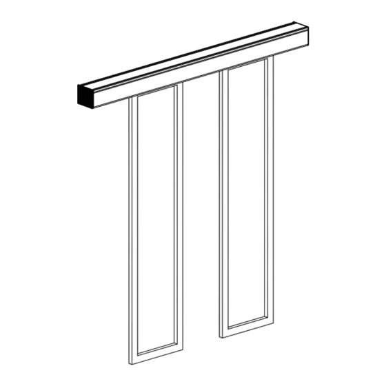
D812061 00200_09 VISTA EMERGENCY -... - Page 6 Motorised crosspiece for automatic single or double leaf sliding doors. Complete with control panel. Accessories for a complete installation available. COMPOSIZIONE DEL KIT - KIT COMPOSITION x 22 x 22 VISTA EMERGENCY ISTRUZIONI D’USO E DI INSTALLAZIONE AUTOMAZIONI PORTE Attenzione! Leggere attentamente le “Avvertenze” all’interno!
- Page 7 Safety sensor and emergency opening Toothed drive belt (see point M) External activation and safety sensor Cable raceway (see point M) Side safety sensor Electronic function selector switch PUSH BUTTON Emergency opening push button Badge for selector switch VISTA EMERGENCY -...
- Page 8 NOTE: all measurements are approximate and expressed in mm. The values shown are calculated considering Loo = 50 mm and Loc = 0 mm. Modello Cinghia (min) A (max) B (max) Model Belt (min) VISTA EMERGENCY 208 1900 2 x 450 3030 VISTA EMERGENCY 209 2000 2 x 500...
- Page 9 NOTE: all measurements are approximate and expressed in mm. The values shown are calculated considering Loo = 50 mm and Loc = 0 mm. Modello Cinghia (min) A (max) B (max) Model Belt (min) VISTA EMERGENCY 107 1600 2200 VISTA EMERGENCY 108 1800 2400 2000...
- Page 10 NOTE: all measurements are approximate and expressed in mm. The values shown are calculated considering Loo = 50 mm and Loc = 0 mm. Modello Cinghia (min) A (max) B (max) Model Belt (min) 1600 2540 VISTA EMERGENCY 107 VISTA EMERGENCY 108 1800 2740 VISTA EMERGENCY 109 2000 1000 1030 2940...
- Page 11 HFT= HGP + HA + HT HT= 130 mm HA= Altezza dell’anta finita HGP=Spazio fra pavimento ed anta mobile HA= Height of the finished door leaf HGP=Space between floor and moving door leaf HA= HFT - HGP - HT VISTA EMERGENCY -...
- Page 12 (Ld – 8), comprensiva delle coperture laterali in including the plastic side covers. materiale plastico. FORATURA PER MONTAGGIO TRAVERSA - DRILLING FOR CROSSPIECE INSTALLATION Modello Model 425 (x2) VISTA EMERGENCY 107 400 (x2) VISTA EMERGENCY 108 350 (x3) VISTA EMERGENCY 109 580 (x3) VISTA EMERGENCY 110...
- Page 13 FORATURA PER PASSAGGIO CAVI SUL RETRO DELLA TRAVERSA (OPZIONALE) DRILLING TO ROUTE CABLING ON THE REAR OF THE CROSSPIECE (OPTIONAL) 40.7 Se necessario realizzare un foro sulla traversa per il passaggio dei cavi. If necessary, drill a hole on the crosspiece for cable routing. VISTA EMERGENCY -...
- Page 14 Non in dotazione / Not supplied: Max 5mm Verificare la planarità del muro tramite una pertica. Predisporre eventuali spessori o piastre di livellamento. Use a straight edge to check the flatness of the wall. Arrange any necessary shims or levelling plates. 14 - VISTA EMERGENCY...
- Page 15 16 mm grigio) alla traversa in alto, allineandola alle altre due. MONTAGGIO CARRELLI DI SCORRIMENTO E SUPPORTO Rest the pulley (in grey) INSTALLATION OF SLIDING AND SUPPORT HANGERS upward onto the crosspiece, aligning it with the other two. VISTA EMERGENCY -...
- Page 16 MONTAGGIO STAFFE DI FINECORSA INSTALLATION OF LIMIT STOP BRACKETS SINISTRA DESTRA LEFT RIGHT MONTAGGIO MOTORE E UNITÀ DI CONTROLLO MOTOR AND CONTROL UNIT INSTALLATION 16 - VISTA EMERGENCY...
- Page 17 GUIDE PULLEY BELT INSTALLATION AND ADJUSTMENT ≈18 mm Verificare manualmente che la tensione della cinghia non risulti troppo tesa oppure troppo lasca. Manually check to ensure that the belt tension is neither too tight nor too loose. VISTA EMERGENCY -...
- Page 18 MONTAGGIO CINGHIA BELT INSTALLATION MONTAGGIO BATTERIE BATTERY INSTALLATION 18 - VISTA EMERGENCY...
- Page 19 INSTALLAZIONE ANTE-DOOR LEAF INSTALLATION REGOLAZIONE ALTEZZA ANTA, ADJUSTING DOOR HEIGHT -8 mm +8 mm REGOLAZIONE TRASVERSALE ANTA, ADJUSTING DOOR CROSSWISE +7 mm -7 mm VISTA EMERGENCY -...
- Page 20 90° sormonto fra anta mobile e parte fissa. Ø 7,5 overlapping spa- ce between mo- Ø 3,5 ving door leaf and -4 mm fixed part Ø 3,5 +4 mm REGOLAZIONE BATTUTE DI FINECORSA-ADJUSTMENT OF LIMIT STOPS 20 - VISTA EMERGENCY...
- Page 21 Non in dotazione. Not supplied. VISTA EMERGENCY -...
- Page 22 Bistable locking device BBE Dispositivo di blocco bistabile BBE Magnetic brake - guide pulley FME Freno magnetico - puleggia rinvio FME 1-S1 BBE lock signalling device for emergency exits Dispositivo di segnalazione blocco BBE per uscite di 1-S1 emergenza 22 - VISTA EMERGENCY...
- Page 23 Pulsante di scorrimento del menù e di aumento dei valori selezionati. Pulsante di scorrimento del menù e di riduzione dei valori selezionati. ENTER Pulsante di selezione del menù e di salvataggio dei dati selezionati. Pulsante di uscita dal menù. VISTA EMERGENCY -...
- Page 24 Non collegare ROSA ROSA Per ulteriori informazioni, fare riferimento al manuale di installazione del sensore. D102 IT – 2020 06 01 30 www.facesp 6A (6B) GRIGIO ROSSO ROSSO OPEN ENTER GIALLO Non collegare SAFETY BIANCO Non collegare Per ulteriori informazioni, fare riferimento al manuale di installazione del sensore. 24 - VISTA EMERGENCY Collegare il sensore, mediante il cavo in dotazione, ai morsetti del controllo elettronico come segue: ...
- Page 25 ‐ 5 lampeggi = malfunzionamento del controllo elettronico Emergency ‐ 5 lampeggi = malfunzionamento del controllo elettronico Emergency ‐ 5 lampeggi = malfunzionamento del controllo elettronico Emergency ‐ 5 lampeggi = malfunzionamento del controllo elettronico Emergency D102 IT – 2020 06 01 27 www.facespa.it ‐ 4 lampeggi = sovratemperatura del motore. VISTA EMERGENCY - ‐ 5 lampeggi = malfunzionamento del controllo elettronico Emergency D102 IT – 2020 06 01 27 www.facespa.it D102 IT – 2020 06 01 D102 IT – 2020 06 01 27 27 www.facespa.it www.facespa.it D102 IT – 2020 06 01 27 www.facespa.it D102 IT – 2020 06 01 27 www.facespa.it ...
- Page 26 UNLK = il dispositivo di blocco si sgancia e la porta rimane ferma. N.B. Se la porta automatica viene spenta per lunghi periodi, scollegare la batteria dalla scheda elettronica. FIRE = chiusura prioritaria della porta per allarme fuoco 26 - VISTA EMERGENCY...
- Page 27 NO = vedere impostazione MENU > PUSH (stessa forza in apertura e in chiusura) PUSH valore minimo = 1 valore massimo = 10 N.B. Se necessario, è possibile impostare la forza di chiusura (PC) diversa dalla forza di apertura (PUSH). VISTA EMERGENCY -...
- Page 28 SECL = TAG), - attendere 2 minuti oppure premere il tasto ESC. N.B. Se il badge non viene riconosciuto il display visualizza la scritta UNKN. E’ possibile memorizzare complessivamente massimo 50 badges. APP = non utilizzabile. 28 - VISTA EMERGENCY...
- Page 29 NO = il simbolo “porta chiusa” resta illuminato anche se la porta viene aperta a mano. SIGNAL YES = il simbolo “porta chiusa” si illumina solo quando la porta è realmente chiusa e bloccata. N.B. se il blocco non chiude la porta, il simbolo “porta chiusa” lampeggia. VISTA EMERGENCY -...
- Page 30 W034 Errore relè motore Malfunzionamento del controllo elettronico W035 Errore posizione blocco Verificare collegamento blocco - microinterruttore W036 Errore funzionamento blocco Verificare collegamento blocco - microinterruttore W037 Fallimento manovra di apertura Verificare la presenza di ostacoli 30 - VISTA EMERGENCY...
- Page 31 Effettuare le regolazioni del menù come indicato al capitolo F. Usare il tasto OPEN per impartire i comandi di apertura, e verificare il corretto funzionamento della porta. N.B. L’automazione riconosce automaticamente gli eventuali ostacoli durante la manovra di chiusura (inversione del movimento) e di apertura (arresto del movi- mento). VISTA EMERGENCY -...
-
Page 32: Ricerca Guasti
Verificare la regolazione della posizione delle staffe aggancio bloc- si sganciano dal dispositivo di blocco. Tirando la cordina di sblocco non si sbloccano le Verificare il corretto fissaggio della cordina di sblocco sul disposi- ante. tivo di blocco. 32 - VISTA EMERGENCY... - Page 33 Tutti gli interventi di manutenzione, sostituzione, riparazione, aggiornamento, ecc. devono essere scritti nel registro di manutenzione, come richiesto dalla norma europea EN16005, e consegnati al proprietario della porta scorrevole automatica. Per l’eventuale riparazione o sostituzione dei prodotti, dovranno essere utilizzati ricambi originali. VISTA EMERGENCY -...
- Page 34 Buttons Description OPEN Open the door. Scroll the menu and increase of selected values. Scroll the menu and reduction of selected values. ENTER Button to select the menu and save the selected data. Exit the menu. 34 - VISTA EMERGENCY...
- Page 35 Verde Non collegare Pink Pink Per ulteriori informazioni, fare riferimento al manuale di installazione del sensore. D102 IT – 2020 06 01 30 www.facesp 6A (6B) Gray OPEN ENTER Yellow Do not connect SAFETY White Do not connect For more information, check the installation manual of the sensor. VISTA EMERGENCY - Collegare il sensore, mediante il cavo in dotazione, ai morsetti del controllo elettronico come segue: ...
- Page 36 D102 IT – 2020 06 01 27 www.facespa.it ‐ 4 lampeggi = sovratemperatura del motore. D102 IT – 2020 06 01 27 www.facespa.it 36 - VISTA EMERGENCY D102 IT – 2020 06 01 ‐ 5 lampeggi = malfunzionamento del controllo elettronico Emergency 27 www.facespa.it D102 IT – 2020 06 01 27 www.facespa.it D102 IT – 2020 06 01 D102 IT – 2020 06 01 27 27 www.facespa.it www.facespa.it ...
- Page 37 UNLK = the locking device is released and the door remains stationary. Note: If the automatic door is turned off for long periods, disconnect the battery from the electronic board. FIRE = priority closing of the door for fire alarms. VISTA EMERGENCY -...
- Page 38 NO = see MENU > PUSH setting (same force for opening and closing) PUSH minimum value = 1 maximum value = 10 NOTE: If necessary, the closing force (PC) can be set differently from the opening force (PUSH). 38 - VISTA EMERGENCY...
- Page 39 -wait for 2 minutes or press the ESC button. Note: if the badge and the numeric code is not recognized the display shows the message UNKN. You can store a total maximum of 50 badges. APP = not usable. VISTA EMERGENCY -...
- Page 40 YES = the symbol “closed door” lights up only when the door is really closed and locked. Note: if the locking device does not close the door, the symbol “closed door” flashes. Note: if the locking device does not close the door, the symbol “closed door” flashes 40 - VISTA EMERGENCY...
- Page 41 W034 Relay motor error Electronic control failure W035 Error lock position Check the lock and microswitch connections W036 Error of lock operation Check the lock and microswitch connections W037 Opening door failure Check the presence of obstacles VISTA EMERGENCY -...
- Page 42 Perform the menu settings as described in Chapter 8. Use OPEN button to perform the opening door, and verify the correct operation of the door. Note: the automation automatically detects any obstacles during the closing movement (reversal movement) and opening (stopping movement). 42 - VISTA EMERGENCY...
-
Page 43: Troubleshooting
The attachment lock brackets, fixed on carriage, will Check the adjustment of the position of the brackets coupling not release lock. Pulling the release cord don’t unlock the doors. Check the correct fitting of the release cord on the lock. VISTA EMERGENCY -... - Page 44 All maintenance, replacement, repair, update, etc.. must be written into the proof book, as required by European standard EN16005, and delivered to the owner of the automatic sliding door. For repairs or replacements of products, original spare parts must be used. 44 - VISTA EMERGENCY...
- Page 45 Funzionamento continuo Continuous operation Classe di servizio Intermittenza Duty class Intermittent operation S3 = 100% S3 = 100% Memoria di salvataggio dei dati Memory for settings and USB standard USB standard e delle regolazioni della porta saving VISTA EMERGENCY -...
- Page 46 MONTAGGIO E MESSA A TERRA CARTER - INSTALLATION AND EARTHING THE GUARD TRAVERSA CROSSPIECE CARTER GUARD Cavo di terra con occhielli alle estremità Messa a terra Carter Earth cable with eyelets at each end Guard earthing 46 - VISTA EMERGENCY...
- Page 47 MONTAGGI GOMMINI ANTIVIBRAZIONE CARTER - INSTALLATION OF GUARD RUBBER VIBRATION DAMPERS VISTA EMERGENCY -...
Need help?
Do you have a question about the VISTA EMERGENCY and is the answer not in the manual?
Questions and answers