Advertisement
Quick Links
Advertisement

Related Manuals for Intense 951 TRAIL 2023


Summary of Contents for Intense 951 TRAIL 2023
- Page 1 2023...
- Page 2 REGISTER YOUR BIKE AT: www.intensecycles.com/pages/registerbike FOR TECHNICAL ASSISTANCE: Email info@intensecycles.com Phone +1 951-307-9211...
-
Page 3: Table Of Contents
WELCOME TO THE INTENSE FAMILY! CONGRATULATIONS ON YOUR NEW INTENSE 951 TRAIL BIKE! AT INTENSE WE HAVE ONE GOAL - TO PROVIDE THE RIDE OF YOUR LIFE! CONTENTS 04-05 Getting to know your bike 06-07 Getting to know your tools... -
Page 4: Getting To Know Your Bike
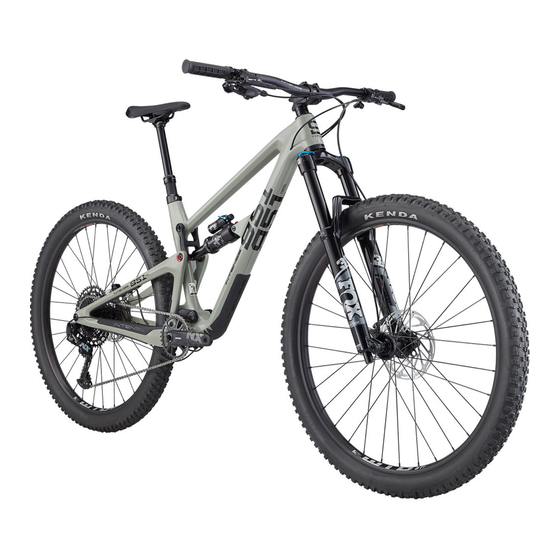
GETTING TO KNOW YOUR BIKE Featuring a lightweight full carbon frame, rolling on 29” wheels, and with 140/150mm of suspension travel the INTENSE 951 TRAIL is the ultimate all-round mountain bike… in fact it might be the only bike you’ll ever need. SADDLE... - Page 5 HANDLEBARS GRIPS STEM DROPPER POST LEVER SHIFTER TOPTUBE DOWNTUBE BRAKE LEVERS fork AIR VALVE CAP (TOP OF LEFT LEG) HEADTUBE fork COMPRESSION DAMPING ADJUSTER (TOP OF RIGHT LEG) fork rebound adjuster FORKs WHEEL HUB LOWER SUSPENSION LINK FLAK GUARD Bottle CAGE MOUNTS BRAKE...
-
Page 6: Getting To Know Your Tools
(4mm, 5mm, 6mm) 9. Flat head driver 19. Torx 25 tool 10. 6mm HEX/Allen driver 20. INTENSE Shock Pump 11. 8mm HEX/Allen driver WANT TO GO TUBELESS? Your WTB wheels are tubeless ready and you will find two small bottles of tubeless sealant, one for each wheel contained within the bike box. - Page 7 w ww. in te ns e9 51. com...
-
Page 9: Setup Guide
INTENSE 951 TRAIL SETUP GUIDE Your new 951 TRAIL is almost ready to go, you just need to do a few things to get your bike ready for the ride. - Page 10 STEP 01 REMOVE WHEELS AND PREPARE BIKE The packaging sections are individually Remove the toolbox and accessories numbered to make it easy for you to and place nearby. Carefully remove the remove everything in the right order. The wheels wheels from the bike box and put to one side. come out first, followed by the rest of the bike.
- Page 11 Replace the faceplate of the stem and When tightening the bolts follow this reinsert the bolts, firstly by hand and pattern to ensure even clamping: top then with the 4mm Allen key. Gradually tighten left, bottom right, bottom left, top right. Finish off the bolts, making sure that the bars are still using the torque wrench to 5Nm.
- Page 12 STEP 04 INSTALL DERAILLEUR DERAILLEUR B SCREW Move to the rear of the bike and cut off At this point be careful that the notch any zip-ties or packaging from the rear on the ‘B screw’ is positioned correctly derailleur and chain. Using a 5mm Allen key, screw (see above) so that it sits on the flat notch on the the derailleur into the derailleur hanger/frame.
- Page 13 STEP 05 INSTALL THE REAR WHEEL POSITION AT 70° TO THE AXLE Remove the plastic brake pad spacer. There is a integrated metal lever that sits Once this is removed be careful not to inside the axle. Pull this out, position at squeeze the brake lever until the rear wheel is in 70°...
- Page 14 PUSH TOWARD THE FRONT OF THE BIKE INSERT AXLE FROM THE NON-DRIVE SIDE Once everything is lined up and in Now take the lock off the rear derailleur. position, reinsert the axle. Tighten the axle To do this, gently push the derailleur using the integrated lever on the non-drive side cage forward a little.
- Page 15 STEP 07 INSTALL THE PEDALS PEDAL LABEL Bicycles have specific left and right The left-hand side (non-drive side) pedals, and the left-hand side pedal has pedal tightens up in a counterclockwise an opposite thread on it. You need to make sure direction.
- Page 16 STEP 09 ADJUST HEADSET & HANDLEBARS It is now time to flip your bike over onto Once you are happy with your headset its wheels and check that your headset adjustment you need to make sure that is adjusted correctly. Set your headset preload your stem and handlebars are straight.
- Page 17 STEP 11 ADJUST SADDLE HEIGHT Set the height of your saddle (seat) with your seatpost in its fully extended position. Using a 4mm Allen key loosen the seatpost clamp and adjust the seatpost to the correct height. A good base measurement is to stand next to your bike in riding shoes, putting your hand against the top of your hip bone the palm of your hand should be level with the top of the saddle.
- Page 18 STEP 14 FOX RHYTHM 36 FLOAT FRONT SUSPENSION SETUP 150 MM. GRIP DAMPER AIR VALVE CAP. TO UNSCREW TURN COUNTERCLOCKWISE The next thing you need to do is set Remove the blue top cap on the left up your suspension. The 951 TRAIL leg of your fork (non-drive side).
- Page 19 The recommended settings below are designed to be a starting point, in order to get you out on your first ride in as few steps as possible. As you ride and get used to your new fork, adjust your settings as explained in step 13. SUGGESTED STARTING POINTS FOR SETTING FORK SAG ADJUSTING...
- Page 20 STEP 15 FOX PERFORMANCE FLOAT X. REAR SUSPENSION SETUP 2-POSITION (OPEN/FIRM) AIR VALVE CAP. TO UNSCREW TURN COUNTERCLOCKWISE RUBBER O-RING Now do the same for the rear shock. The Schrader valve is easier to see, so unscrew the cap and pump it up using the high-pressure air shock pump to the pressure shown in the chart opposite for your weight.
- Page 21 SUGGESTED STARTING POINTS FOR SETTING UP YOUR SHOCK RIDER WEIGHT AIR PRESSURE REBOUND (lbs/kgs) (psi) (clicks out from fully closed) Closed is Clockwise Open is Counterclockwise COMPRESSION <100lbs / 45kgs ADJUSTMENTS 100lbs / 45kgs The 2-position lever is 110lbs / 50kgs useful to make on-the-fly 120lbs / 54kgs adjustments to control...
-
Page 22: Geometry Guide To Flip Chip
GEOMETRY GUIDE TO FLIP CHIP The 951 TRAIL has a great feature called a ‘Flip Chip’. The Flip Chip allows you to alter the geometry of the bike in one of two positions. The 951 TRAIL comes from our factory as standard in the High setting. - Page 23 TRAIL HIGH SETTING (MM / INCH) SIZE SMALL MEDIUM LARGE EXTRA LARGE WHEELBASE (A) 1179 mm/ 46.4" 1209 mm/ 47.6" 1239 mm/ 48.8" 1271mm / 50” TOPTUBE LENGTH (B) 568 mm/ 22.4" 598 mm/ 23.5" 626 mm/ 24.7" 657 mm/ 26" CHAINSTAY LENGTH (C) 441 mm/ 17.4"...
- Page 24 FRAME SPECS Model: INTENSE 951 SERIES TRAIL Compatible Forks: 150mm Travel Headtube/Headset: zs44/28.6 - ec49/40 Frame Seattube Dimensions: OD 35.6mm (OD = Outside Diameter) ID 31.6mm (ID = Inside Diameter) Seattube Diameter: 31.6mm BB Shell Width: 73mm, BSA Threaded Recommended Max Tire Size: 2.4"...
- Page 25 TIRES Kenda Pinner 29” x 2.40” PEDALS Platform SEATPOST INTENSE Recon Dropper 125mm Travel (S), 150mm Travel (M,L), 170mm Travel (XL) SADDLE (SEAT) Fizik Terra Alpaca X5, Alloy Rails COMPONENT MANUAL ONLINE RESOURCE We have a full resource available online for all of the parts fitted to this bike.
-
Page 26: Maintenance
If you discover damage in any degree it’s best to have your frame inspected by a qualified INTENSE, LLC dealer. Any direct impact to the frame can cause serious structural damage. • Use high-grade waterproof grease on seat post, BB and headset bearing contact areas with the carbon. - Page 27 MAINTENANCE SCHEDULE Action Every Ride 500 Miles 2000 Miles 4000 Miles or 1 Month or 6 Months 1 Year TIRES Check air pressure, inspect tread and sidewalls for tears and punctures CHAIN Brush off and lubricate BRAKES Squeeze brakes and confirm function GENERAL Clean complete bike of mud and debris HEADSET...
-
Page 28: Parts Listings
INTENSE 951 TRAIL PARTS LISTINGS... - Page 29 21 O-Ring 140044 O-Ring 13.8 mm ID x 2.4 mm Width 22 Seat Clamp 340340 Seat Clamp Forged Fin Style INTENSE 23 Zerk Fitting M6 x 1.0 401011 Zerk Fitting M6 x 1.0 5Nm / 45in-lbs 24 BHCS M5 X 12...
-
Page 30: Parts Kits
INTENSE 951 TRAIL PARTS KITS AXLE KIT IT150125 Axle Kit Rear CNC 148 x 12 Boost With Hidden Lever 951 Series TRAIL 130899 M12 x P1.0 x 172mm (148 x 12mm) QR491, Wheel Axle Kit BEARING KIT LOWER IT340193 Bearing Rebuild Kit Lower 951 Series TRAIL... - Page 31 SEAT COLLAR IT150184 Seat Collar Bolted 951 Series TRAIL 340340 Seat Clamp 410079 SHCS, Socket Head, M6 x 18 HARDWARE KIT UPPER IT150185 Link Kit Upper Hardware 951 Series TRAIL 130785 Shoulder Bolt Fine Thread 130813 RT D-Lock Bolt 130814 Drive Side RT Nut 130821 Spacer with O-ring groove...
- Page 32 N E E D H E L P ? DO NOT RETURN TO THE STORE call us at: +1 951.307.9211 or email: info@intensecycles.com our rider support team looks forward to helping with any questions.
Need help?
Do you have a question about the 951 TRAIL 2023 and is the answer not in the manual?
Questions and answers