Graco Dura-Flo 1100 Manual
Hide thumbs
Also See for Dura-Flo 1100:
- Instructions manual (16 pages) ,
- Instructions and parts list (24 pages)
Table of Contents
Advertisement
Quick Links
INSTRUCTIONS–PARTS LIST
CARBON STEEL
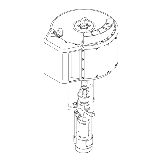
Dura-Flo
With Severe-Duty Rod and Cylinder
Part No. 236–932 Pump, Series A,
74:1 Ratio, with Premier
510 bar (7400 psi) Maximum Fluid Working Pressure
7 bar (100 psi) Maximum Air Input Pressure
Refer to page 2 for Table of Contents.
GRACO INC. P.O. BOX 1441 MINNEAPOLIS, MN 55440–1441
This manual contains important
warnings and information.
READ AND RETAIN FOR REFERENCE
1100 Pumps
Air Motor
COPYRIGHT 1994, GRACO INC.
308–357
Rev A
03632
Advertisement
Table of Contents

Subscribe to Our Youtube Channel
Related Manuals for Graco Dura-Flo 1100


Summary of Contents for Graco Dura-Flo 1100
- Page 1 74:1 Ratio, with Premier Air Motor 510 bar (7400 psi) Maximum Fluid Working Pressure 7 bar (100 psi) Maximum Air Input Pressure Refer to page 2 for Table of Contents. 03632 GRACO INC. P.O. BOX 1441 MINNEAPOLIS, MN 55440–1441 COPYRIGHT 1994, GRACO INC.
-
Page 2: Table Of Contents
... . . 14–17 Graco Phone Numbers ...... -
Page 3: Warnings
WARNINGS High Pressure Spray Can Cause Serious Injury. For Professional Use Only. Observe All Warnings. Read and understand all instruction manuals before operating equipment. FLUID INJECTION HAZARD General Safety Tip Guard (only on spray guns) This equipment generates very high fluid pressure. Spray Always have the tip guard in place on the gun while spraying. - Page 4 EQUIPMENT MISUSE HAZARD General Safety System Pressure Any misuse of the spray/dispensing equipment or accesso- Never exceed the recommended working pressure or the ries, such as overpressurizing, modifying parts, using incom- maximum air inlet pressure stated on your pump or in the Technical Data on page 22.
- Page 5 Do not expose beneath the rocker arm covers) move when air is supplied to Graco hoses to temperatures above 82 C (180 F) or below the motor. Never operate the pump with the rocker arm cov- –40 C (–40 F).
-
Page 6: Installation
Graco representative or Graco Technical Assistance (see back page) for assistance in designing a system NOTE: Accessories are available from your Graco rep- to suit your particular needs. resentative. If you supply your own accessories, be sure they are adequately sized and pressure-rated to meet the system’s requirements. - Page 7 Installation ASSEMBLE THE PUMP A bleed-type master air valve (E) is required in your system to relieve air trapped between it and the air motor when the valve is closed (see the Assemble the displacement pump (105) to the air mo- WARNING above).
-
Page 8: Operation/Maintenance
PACKING NUT/WET-CUP Before starting, fill the packing nut (2) 1/3 full with Graco Throat Seal Liquid (TSL) or compatible solvent. See Fig. 3. The packing nut is torqued at the factory and is ready for operation. If it becomes loose and there is leaking... - Page 9 Operation/Maintenance Starting and Adjusting the Pump 6. Use the air regulator to control the pump speed and the fluid pressure. Always use the lowest air pressure necessary to get the desired results. 1. Refer to Fig. 2 on page 6. Connect the suction kit Higher pressures cause premature tip and pump (T) to the pump’s fluid inlet, and place the tube into wear.
- Page 10 Notes...
-
Page 11: Troubleshooting Chart
Turn on the air just enough to start the pump. If the pump starts when the air is turned on, the obstruction is in the fluid hose or gun. NOTE: If you experience air motor icing, call Graco Technical Assistance (1-800-543-0339). WARNING... -
Page 12: Service
Fill the packing nut (2) 1/3 full of Graco Throat Seal Liquid or compatible solvent. 8. Turn on the air supply. Run the pump slowly to en- sure that it is operating properly. - Page 13 Service Torque to 129–142 N.m (95–105 ft–lb) Torque to 312–340 N.m (230–250 ft–lb) Fig. 4...
-
Page 14: Displacement Pump Service
Service DISPLACEMENT PUMP SERVICE 5. Lift the cylinder (11), displacement rod (1), and piston assembly off the intake housing (16). Re- Disassembly move the ball guide (27) from the intake housing, and inspect the guide surfaces. See Fig. 6. When disassembling the pump, lay out all the removed parts in sequence, to ease reassembly. - Page 15 Service 9. Examine the displacement rod (1) for scratches or other damage. Only if the rod needs replace - ment, unscrew it from the piston ball housing (12), using an adjustable wrench on the flats of the rod. 10. Remove and inspect the glands and v-packings (P) from the piston seat housing (14).
- Page 16 Service Reassembly 7. Place the intake ball guide (27) in the intake hous- ing (16). Set the intake housing in the vise, facing 1. If it was necessary to remove the piston ball hous - upright. See Fig. 6. ing (12) from the displacement rod (1), clean the threads of the rod and the ball housing, and apply 8.
- Page 17 Service Torque to 129–142 N.m (95–105 ft–lb). Torque to 522–542 N.m (385–400 ft–lb). Torque to 386–407 N.m (285–300 ft–lb). Lubricate. Apply thread sealant. Lips face up. Lips face down. See Throat Packing Detail at left. See Piston Packing Detail at left. Torque to 244–264 N.m (180–195 ft–lb).
-
Page 18: Parts Drawings And Parts Lists
Parts Part No. 236–932 Pump, Series A Ref. Part No. Description Qty. 74:1 Ratio, with Premier Air Motor 222–800 AIR MOTOR, Premier See 308–213 for parts 184–581 ADAPTER, connecting rod 184–098 NUT, coupling 112–887 WRENCH, spanner 236–478 PUMP, displacement See page 19 for parts 106–166 NUT, hex;... -
Page 19: Displacement Pump
Parts Displacement Pump 236–478, Series A Part Part Description Description 222–951 HOUSING, seat, piston valve; 189–317 ROD, displacement; stainless steel stainless steel w/tungsten carbide seat 1 222–995 PACKING NUT; carbon steel 108–001 BALL, intake; stainless steel; 172–477 TAG, warning (not shown) 1.5”... -
Page 20: Repair Kits
Repair Kits Standard Repair Kit 237–166 Packing Conversion Kit 237–168 PTFE (Leather Packings and Backup) (UHMWPE and Leather Packings) Part Part Description Description PTFE 109–306 V-PACKING; 109–256 V-PACKING; UHMWPE 184–201 GLAND, female; carbon steel 184–201 GLAND, female; carbon steel 184–306 V-PACKING;... - Page 21 Notes...
-
Page 22: Technical Data
Technical Data (MODEL 236–932 PREMIER PUMP) WARNING Be sure that all fluids and solvents used are chemically compatible with the Wetted Parts listed below. Always read the manufacturer’s literature before using fluid or solvent in this pump. Ratio ............... 74:1 Maximum fluid working pressure . -
Page 23: Dimensions
Dimensions Mounting Hole Layout Premier Pumps 135.0 mm 67.5 mm (5.3 in.) (2.7 in.) 116.9 mm (4.6 in.) 87.9 mm (3.5 in.) Three M16 x 2.0 Holes 101.5 mm 50.7 mm (4.0 in.) (2.0 in.) 02246 03632 Pump Model 236–932 1146.9 mm 746.0 mm 400.9 mm... -
Page 24: Warranty
Graco distributor to the original purchaser for use. As purchaser’s sole remedy for breach of this warranty, Graco will, for a period of twelve months from the date of sale, repair or replace any part of the equipment proven defec- tive. - Page 25 3X8–357 Rev. B Supersedes Rev. A Parts Change Notice Some parts in Rev. A of manual 308–357 have changed but have not yet been changed in the instruction manual. Please note the changes below and mark them in your manual or keep this sheet with your manual.
Need help?
Do you have a question about the Dura-Flo 1100 and is the answer not in the manual?
Questions and answers