Sign In
Upload
Manuals
Brands
COBHAM Manuals
Antenna
Sea Tel 6011-4
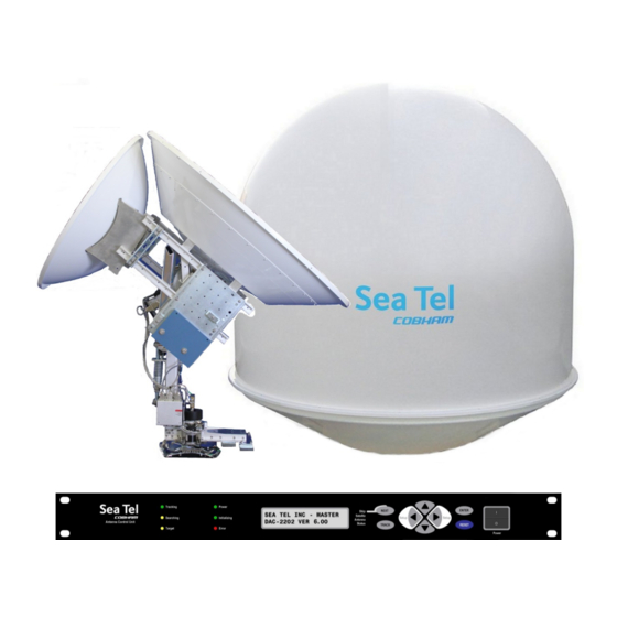
COBHAM Sea Tel 6011-4 Manuals
Manuals and User Guides for COBHAM Sea Tel 6011-4. We have
1
COBHAM Sea Tel 6011-4 manual available for free PDF download: Installation Manual
COBHAM Sea Tel 6011-4 Installation Manual (143 pages)
C/Ku-Band TVRO Satellite Antenna
Brand:
COBHAM
| Category:
Antenna
| Size: 6 MB
Table of Contents
Table of Contents
5
Safety
11
System Cables
13
System
13
Simplified Block Diagram of a 6011-4 System
13
Site Survey - Shipboard
15
Site Selection Aboard the Ship
15
Antenna Shadowing (Blockage) and RF Interference
15
Mounting Foundation
16
Mounting on Deck or Deckhouse
16
ADE Mounting Considerations
16
Sizing of the Support Pedestal
16
Mounting Height
17
Mast Configurations
17
Vertical Masts
17
Raked Masts
18
Girder Masts
19
Truss Mast
19
Safe Access to the Ade
19
Below Decks Equipment Location
19
Cables
20
ADE/BDE Coaxial Cables
20
Antenna Power Cable
20
ACU Power Cable/Outlet
21
Gyro Compass Cable
21
Grounding
21
Installation
23
Unpacking and Inspection
23
Assembly Notes and Warnings
23
Installing the Ade
24
Prepare the 40", 50", 60", 66" or 76" Radome Assembly
24
Install 76" Radome to the Mounting Platform
25
Grounding the Pedestal
28
Removing the Shipping/Stow Restraints PRIOR to Power-Up
28
Removing the AZ Shipping/Stow Restraint
29
Removing the el Shipping/Stow Restraint
29
Removing the CL Shipping/Stow Restraint
31
Cable Installation
32
Shipboard Cable Installation
32
ADE-BDE if Cable Assignments
32
Installing the below Decks Equipment
32
General Cautions & Warnings
32
Preparing BDE Location
32
Installing the below Deck Equipment
32
Connecting the below Decks Equipment
33
Connecting the ADE AC Power Cable
33
Connecting the BDE AC Power Cables
33
Connecting the ADE-BDE if Coaxes
33
Antenna Control Unit Connections
33
Terminal Mounting Strip (TMS) Connections
34
Final Checks
35
Visual/Electrical Inspection
35
Electrical - Double Check Wiring Connections
35
Power-Up
35
Maintenance
35
Balancing the Antenna
35
Fine Balance and Monitoring Motor Drive Torque
36
Basic Setup of the Acu
39
Operator Settings
39
Setup Parameter Display and Entry Menus
39
Default Setup Parameters for Your Antenna
39
Save New Parameters
40
Setup - Setting up the Dual Reflectors
41
Optimizing C-Band (Reflector A)
41
Optimizing Ku-Band (Reflector B)
42
Setup - Ships Gyro Compass
43
Gyro Type
43
Updating the Gyro Type Parameter
43
If There Is no Ships Gyro Compass
43
Setup - Tracking Receiver
45
Determining the if Tracking Frequency (FREQ or Mhz)
45
Khz
45
Fec
45
L-Band SCPC Receiver
45
Tone
45
TVRO Applications
45
Volt
46
TVRO Application
46
Skew
46
Nid
46
Setup - Band & Reflector Select
47
Band, Low Noise Block Converter Operation and Reflector Selection
47
Setup - Targeting
49
Optimizing Qor Dual Reflector Targeting
49
Optimizing C-Band (Reflector A) Targeting
49
Optimizing Ku-Band (Reflector B) Targeting
49
Auto Trim
50
Manually Optimizing Targeting
50
El Trim
51
Az Trim
51
Setup - Home Flag Offset
53
Electronic Calibration of Relative Antenna Position (Home Flag Offset)
53
You Found a Large AZ TRIM Value
54
You Observe "Home" Pointing Is LEFT of the Bow-Line
54
You Observe "Home" Pointing Is RIGHT of the Bow-Line
55
To Enter the HFO Value in the DAC_2202
55
Mechanical Calibration of Relative Antenna Position (Home Flag Offset)
56
Searching Operation
59
Default Standard (Box) Search Pattern
59
Inclined Orbit Search Pattern
60
No Gyro Search Pattern
61
Changing the Search Parameters
62
Auto Thres
62
El Step Size
62
Az Step Size
63
Step Integral
63
Search Inc
63
Search Limit
63
Search Delay
63
Sweep Inc
64
Save New Parameters
64
Setup - Blockage & Rf Radiation Hazard Zones
65
Radiation Hazard and Blockage Mapping (AZ LIMIT Parameters)
65
Save New Parameters
69
Setup - Other Parameters
71
Setup Parameter Display and Entry Menus
71
OFFSET (May Not be in Your Software)
71
SCALE (May Not be in Your Software)
71
Remote Command
71
Remote Monitor
71
To Disable/Enable Dishscan
71
Satellite Reference Mode
72
Remote Parameters
72
Stowing the Antenna
73
Installing the Stow Restraints
73
Installing the AZ Shipping/Stow Restraint
73
Installing the el Shipping/Stow Restraint
74
Installing the CL Shipping/Stow Restraint
75
Removing the Shipping/Stow Restraints PRIOR to Power-Up
76
Removing the AZ Shipping/Stow Restraint
76
Removing the el Shipping/Stow Restraint
77
Removing the CL Shipping/Stow Restraint
78
Operation
81
Target a C-Band Satellite
81
Target Froma C-Band Satellite T O Another C-Band Satellite
82
Target a Ku-Band Satellite from a C-Band Satellite
84
Target from a Ku-Band Satellite to Another Ku-Band Satellite
86
System
88
Functional Testing
89
Acu / Antenna System Check
89
Latitude/Longitude Auto-Update Check
89
Heading Following
89
Blockage Simulation Test
90
Four Quadrant Tracking Test
90
Installation Troubleshooting
93
Warranty Information
93
Troubleshooting the Acu
93
ACU Display Is Blank
93
ACU Status Displays "REMOTE NOT RESPONDING
94
Troubleshooting Ships Gyro Compass Problems
94
Step-By-Step
94
1:1 Synchro
94
360:1 Synchro
95
Maintenance
97
C-Band Feed Assembly Polarity Selection
97
Replacing the Ku-Band LNB
98
Replacing or Changing Lnbs
98
Optimizing Ku-Band Linear Polarization
100
Bluetooth Installation & Operation
101
Prerequisites
101
Installing the Ade Bluetooth Hardware
101
Installing the Bde Bluetooth Hardware
102
Diagnostic Mode
102
Removing the Ade Bluetooth Hardware
103
Removing the Bde Bluetooth Hardware
103
Installing Software Via Bluetooth
104
Normal Operation Mode
104
Tvro Technical Specifications
105
Stabilized Antenna Pedestal Assembly
105
Qor Tm Dual Reflector Configuration
106
Antenna Assembly - 60" C-Band TVRO
106
Antenna Assembly - 40" Ku-Band TVRO
106
Interchangeable Lnb Options
107
C-Band Lnbs
107
Circular LNB
107
DLA Circular LNB
107
European Quad Universal Linear LNB
107
Mk 2 Pedestal Control Unit (Pcu)
108
Mk 2 Motor Driver Enclosure (Mde)
108
Mh Z Base & Pedestal Unlimited Azimuth Modems (3 Channel )
109
Radome Assembly , 76
109
Ade Pedestal Power Requirements
110
Environmental Specifications
110
Climatic Conditions
110
Chemically Active Substances
110
Transit Conditions
110
Below Decks Equipment
111
Antenna Control Unit (ACU)
111
Terminal Mounting Strip (TMS)
111
Satellite Receiver
111
Multiswitch
111
Cables
111
Antenna Control Cable (Provided from ACU to the Base MUX)
111
Antenna L-Band TVRO if Coax Cables (Customer Furnished)
111
Multi-Conductor Cables (Customer Furnished)
112
Drawings
113
6011-4 Model Specific Drawings
113
Antenna Assy, Circular, C Band, 60 In, Tvro
122
Antenna Assy, 6011-4, 40 In, Ku-Band
124
Balance Weight Assy, Cl/El, 6011-4
128
Procedure, Radome Strain Relief Installation
134
Base Modem Rack Panel Assy, 4Ch Tvro, 400Mhz
142
Advertisement
Advertisement
Related Products
COBHAM Sea Tel 6009-11
COBHAM Sea Tel 6009-17
COBHAM Sea Tel 6009-23
COBHAM Sea Tel 6009-33
COBHAM Sea Tel 6000
COBHAM Sea Tel 4009-23
COBHAM Sea Tel 4009-33
COBHAM Sea Tel 5009-11
COBHAM Sea Tel 131921-1
COBHAM Sea Tel 4010W-33
COBHAM Categories
Antenna
Marine Equipment
Radio
Touch terminals
Receiver
More COBHAM Manuals
Login
Sign In
OR
Sign in with Facebook
Sign in with Google
Upload manual
Upload from disk
Upload from URL