Table of Contents
Advertisement
Quick Links
Advertisement
Table of Contents

Related Manuals for Schmidt SS 23.700 Ex


Summary of Contents for Schmidt SS 23.700 Ex
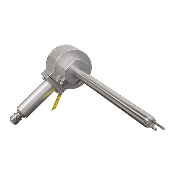
- Page 1 ® SCHMIDT Flow Sensor SS 23.700 Ex Instructions for Use...
-
Page 2: Table Of Contents
® SCHMIDT Flow Sensor SS 23.700 Ex Table of Contents Important information............... 3 Application range - General ............. 4 Application range - ATEX ..............6 Mounting instructions - General ............7 Mounting instructions - ATEX ............17 Electrical connection - General ............. 19 ATEX - Electrical connection and protective sleeve assembly .. -
Page 3: Important Information
2). In particular, it is not designed for direct or indirect protection of personal or machinery. SCHMIDT Technology cannot give any warranty as to its suitability for a certain purpose and cannot be held liable for errors contained in these instructions for use or for accidental or sequential damage in connection with the delivery, performance or use of this unit. -
Page 4: Application Range - General
2 Application range - General ® The SCHMIDT Flow Sensor SS 23.700 Ex (art. no.: 569700) is designed for the stationary measurement of flow velocity as well as the temperature of air and gas with operating temperature from -20 … +120 °C and working pressure up to 16 bar. - Page 5 PWIS-compliant models. Version for “special gases” The version of the SS 23.700 Ex for “special gases” receives a gas-spe- cific adaption for the measurement of certain gases and gas mixtures. The sensor is adjusted and calibrated in air. Then a special correction function for the medium to be measured is applied to the sensor.
-
Page 6: Application Range - Atex
3 Application range - ATEX ® As a category 3 device, the SCHMIDT Flow Sensor SS 23.700 Ex is equipped with the following types of protection: II 3G Ex ec ic IIC T4 Gc o Gases (Zone 2): II 3D Ex ic tc IIIC T135°C Dc... -
Page 7: Mounting Instructions - General
Mounting method The sensor SS 23.700 Ex can be mounted only by means of a compres- sion fitting which supports the sensor tube and ensures frictional clamping. The compression fitting as well as a pressure protection kit is included in the scope of delivery. - Page 8 Correct measurements require a (laminar) flow, low in turbulence. The term “laminar” means here an air flow, low in turbulence (not according to its physical definition saying that the Reynolds number is < 2300). Instructions for Use – SCHMIDT ® Flow Sensor SS 23.700 Ex Page 8...
- Page 9 Installation conditions The sensor head of the SS 23.700 Ex consists of two basic elements: Heater The longer of the two sensor tubes at the tip of the sensor head is the so-called heater. It consists of a heated, temperature-dependent resis- tor that is used to measure flow velocity.
- Page 10 E.g., honeycombs made of plastic or ceramics. Instructions for Use – SCHMIDT ® Flow Sensor SS 23.700 Ex Page 10...
- Page 11 PF. The profile factor depends on the inner pipe diameter (see Table 2). Both inner air friction and sensor locking are responsible. Instructions for Use – SCHMIDT ® Flow Sensor SS 23.700 Ex Page 11...
- Page 12 Profile factor (for pipes with a circular cross-section) V Standard volume flow [m SCHMIDT Technology provides a "flow calculator" on its homepage for the calculation of flow velocity or volume flow in (circular) pipes or (rectan- gular) ducts for the different sensor types: www.schmidt-sensors.com...
- Page 13 �� �� �� Figure 4-4 A uniform flow field prevails in the largest part of the space cross-section. The profile factors are equal for both cross-section forms. Instructions for Use – SCHMIDT ® Flow Sensor SS 23.700 Ex Page 13...
- Page 14 Figure 4-5). Figure 4-5 Probe length [mm] Outer diameter of pipe [mm] Length of weld-in sleeve [mm] Sensor tube setting length [mm] Projecting length [mm] Reference length [mm] Instructions for Use – SCHMIDT ® Flow Sensor SS 23.700 Ex Page 14...
- Page 15 General note: Do not use the alignment plane of the enclosure for mechanical adjustment, e.g. for locking. There is risk of damage to the sensor. Instructions for Use – SCHMIDT ® Flow Sensor SS 23.700 Ex Page 15...
- Page 16 A wall mounting bracket is provided for fastening the sensor enclosure. Accessories ® The accessories required for mounting and operation of the SCHMIDT Flow Sensor SS 23.700 Ex are listed in Table 3 below. Type / Art. no. Drawing Assembly...
-
Page 17: Mounting Instructions - Atex
Minimum cable cross-section: 1 x 4 mm The screw must be tightened firmly at the terminal so that the conductor cannot be loosened or twisted. Instructions for Use – SCHMIDT ® Flow Sensor SS 23.700 Ex Page 17... - Page 18 Peak Figure 5-1 Grounding contacts (red), remote version Figure 5-2 Grounding contacts (red), compact sensor Limitation by varistor inside the sensor between GND and enclosure (ESD-protection). Instructions for Use – SCHMIDT ® Flow Sensor SS 23.700 Ex Page 18...
-
Page 19: Electrical Connection - General
Electromechanical shielding Meshwork Table 4 ® The specified wire colors are valid when one of the SCHMIDT connecting cables is used (see subchapter Accessories, Table 3). The analog signals have an own reference potential “AGND”. Make sure that no supply voltage is active during electrical instal- lation and that it cannot be switched on inadvertently. - Page 20 Operating voltage ® The SCHMIDT Flow Sensor SS 23.700 Ex is protected against reverse polarity of the operating voltage. It requires a DC voltage of 24 V with a tolerance of ±20 % for the intended operation. Operate the sensor only within the specified voltage range and type of 24 V ±...
- Page 21 In case of a short circuit against the negative rail (GND) of the supply is calculated to 0 ) voltage, the output switches to current mode (R and provides the corresponding signal current. „GND“ and „AGND“ are shorted internally Instructions for Use – SCHMIDT ® Flow Sensor SS 23.700 Ex Page 21...
- Page 22 The maximum load capacitance C is 10 nF. A higher capacitance re- duces the limit of the current limiter. Overcurrent peaks are absorbed by the short circuit limiter. Instructions for Use – SCHMIDT ® Flow Sensor SS 23.700 Ex Page 22...
- Page 23 (e.g. due to ESD or surge) of both polarities by means of a TVS diode. The output has no protective measures, exceeding the specified electrical operating values leads to irreversible damage. Transient Voltage Suppressor Diode, breakdown voltage approx. 30 V Instructions for Use – SCHMIDT ® Flow Sensor SS 23.700 Ex Page 23...
-
Page 24: Atex - Electrical Connection And Protective Sleeve Assembly
7 ATEX - Electrical connection and protective sleeve assembly The electrical connection is established by use of special connection ca- bles that are only available from SCHMIDT Technology and which must be purchased additionally as optional accessories: Material numbers: 524921 or 524942... - Page 25 ® (Allen key 2.5 mm; with circlip) Nut of cable bushing (M12, torque < 4 Nm) Figure 7-1 Assembly of connecting cable with protective sleeve Instructions for Use – SCHMIDT ® Flow Sensor SS 23.700 Ex Page 25...
-
Page 26: Atex Type Plate - Labelling
EN 60079-0, chapter 29.6. The side with the warning note „WARNUNG - NICHT UNTER SPANNUNG TRENNEN“ (Meaning: "WARNING - Do not disconnect under voltage") must remain visible. Instructions for Use – SCHMIDT ® Flow Sensor SS 23.700 Ex Page 26... -
Page 27: Signaling
9 Signaling LED bar The Flow Sensor SS 23.700 EX has four Duo-LEDs (see Figure 9-1) in the enclosure cover. They either indicate the flow velocity in fault-free op- eration in a quantitative way (bar graph mode) or they signal the cause of a problem (see Table 5). - Page 28 The measuring range of the corresponding measuring value is mapped in a linear way to the mode-specific signal range of its associated ana- log output. In accordance with the Namur specification. Instructions for Use – SCHMIDT ® Flow Sensor SS 23.700 Ex Page 28...
- Page 29 Table 7). At higher values of w , the output signal remains constant. Error signaling does not take place because damaging of the sensor is unlikely. Instructions for Use – SCHMIDT ® Flow Sensor SS 23.700 Ex Page 29...
- Page 30 The pulse outputs represent the flow velocity w as an alternative to the analog output. The basic version of the SS 23.700 EX maps the flow velocity w pro- portional to a frequency range [0 … f ] with selectable maximum fre- quency f (see Figure 9-3).
- Page 31 If an error occurs, f = 0 Hz resp. no pulses will be output, the actual signal level remains unchanged. Note: The relay can be used as a S0-Interface according EN 62053-31. Former standard: DIN 43 864 Instructions for Use – SCHMIDT ® Flow Sensor SS 23.700 Ex Page 31...
-
Page 32: Commissioning
Environmental condition Temperature ® The SCHMIDT Flow Sensor SS 23.700 EX monitors both the medium and the electronics temperature. As soon as one of the specified operating ranges is left, the sensor switches off both measuring functions associated with the medium and signals the error via its LEDs (according to Table 5). -
Page 33: Service Information
Environmental conditions of medium ® The SCHMIDT Flow Sensor SS 23.700 EX is also suitable for relatively impure gases. Dust or non-abrasive particles can be tolerated as long as they do not form any deposits on the sensor elements. Deposits or other soiling must be detected during regular inspections and removed during cleaning because they can lead to distortion of the meas- urement result (see chapter 12 Service information). - Page 34 +U AGND Analog signal voltage per- Error signaling Eliminate errors manently at zero Short circuit against (A)GND Eliminate short circuit Table 9 Instructions for Use – SCHMIDT ® Flow Sensor SS 23.700 Ex Page 34...
- Page 35 Every new sensor is accompanied by a certificate of compliance according to EN 10204-2.1. Material certificates are not available. Upon request, we shall prepare, at a charge, a factory calibration certifi- cate, traceable to national standards. Instructions for Use – SCHMIDT ® Flow Sensor SS 23.700 Ex Page 35...
-
Page 36: Dimensions
13 Dimensions Compact sensor Figure 13-1 Remote sensor (including wall mounting bracket) Figure 13-2 Instructions for Use – SCHMIDT ® Flow Sensor SS 23.700 Ex Page 36... -
Page 37: Technical Data
- PWIS conform: Stainless steel 1.4571, nickel phosphite (DURNI-COAT Under reference conditions „o. m. v.“: of measured value; „o. f. v.“: of final value > 2 m/s Instructions for Use – SCHMIDT ® Flow Sensor SS 23.700 Ex Page 37... - Page 38 250 / 600 mm 1 … 10 m (steps: 1 m) Cable: Weight Approx. 500 g max. (without connecting cable) Without signal current of pulse output 2 (relay) Instructions for Use – SCHMIDT ® Flow Sensor SS 23.700 Ex Page 38...
-
Page 39: Declarations Of Conformity
15 Declarations of conformity Instructions for Use – SCHMIDT ® Flow Sensor SS 23.700 Ex Page 39... - Page 40 Instructions for Use – SCHMIDT ® Flow Sensor SS 23.700 Ex Page 40...
-
Page 41: Type Examination Certificate
16 Type Examination Certificate Instructions for Use – SCHMIDT ® Flow Sensor SS 23.700 Ex Page 41... - Page 42 Instructions for Use – SCHMIDT ® Flow Sensor SS 23.700 Ex Page 42...
- Page 43 Instructions for Use – SCHMIDT ® Flow Sensor SS 23.700 Ex Page 43...
- Page 44 SCHMIDT Technology GmbH Feldbergstr. 1 78112 St. Georgen Germany Phone +49 (0)7724 / 899-0 +49 (0)7724 / 899-101 Email sensors@schmidttechnology.de www.schmidt-sensors.com www.schmidttechnology.de Instructions for Use – SCHMIDT ® Flow Sensor SS 23.700 Ex Page 44...
Need help?
Do you have a question about the SS 23.700 Ex and is the answer not in the manual?
Questions and answers