Table of Contents
Advertisement
Quick Links
Advertisement
Table of Contents

Related Manuals for Schmidt SS 20.600


Summary of Contents for Schmidt SS 20.600
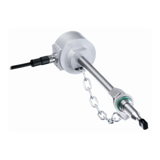
- Page 1 ® SCHMIDT Flow Sensor SS 20.600 Instructions for Use...
-
Page 2: Table Of Contents
® SCHMIDT Flow Sensor SS 20.600 Table of Contents Important information............... 3 Application range ................4 Mounting instructions............... 7 Electrical connection..............20 Signaling ..................25 Commissioning ................30 Information concerning operation ..........31 Service information ................ 32 Dimensions ..................36 Technical data ................ -
Page 3: Important Information
2). In particular, it is not designed for direct or indirect protection of personal or machinery. SCHMIDT Technology cannot give any warranty as to its suitability for a certain purpose and cannot be held liable for errors contained in these instructions for use or for accidental or sequential damage in connection with the delivery, performance or use of this unit. -
Page 4: Application Range
2 Application range ® The SCHMIDT Flow Sensor SS 20.600 (art. no.: 524 600) is designed for stationary measurement of the flow velocity as well as the temperature of pure air and gas with operating temperature up to 120 °C and working pressure up to 40 bar. - Page 5 This standard may be restricted by: Special conditions regarding the use of diatomic oxygen (O The operating specifications of the SS 20.600 with regard to: - Maximum overpressure of the medium of 20 bar. - Maximum temperature of the medium of 60 °C.
- Page 6 Version Special gases The “Special gas” version of the SS 20.600 is equipped with a correction for the measurement of certain gases and gas mixtures. The sensor is adjusted and calibrated in air. Then a special correction for the medium to be measured is applied to the sensor. Those corrections have been determined for many gases in real gas ducts.
-
Page 7: Mounting Instructions
Mounting method The sensor SS 20.600 can be mounted only by means of a compression fitting which supports the sensor tube and ensures positive clamping. The compression fitting as well as a pressure protection kit is included in the scope of delivery. - Page 8 Systems with overpressure Depending on the ordered version, the SS 20.600 is designed for a maxi- mum working overpressure of 16 bar (standard) or 40 bar (option). As long as the medium to be measured is operated with overpressure, make sure that: ...
- Page 9 Correct measurements require a (laminar) flow low in turbulence. The term “laminar” means here an air flow low in turbulence (not according to its physical definition saying that the Reynolds number is < 2300). Instructions for Use – SCHMIDT ® Flow Sensor SS 20.600...
- Page 10 General installation conditions The sensor head of the SS 20.600 consists of two basic elements: The enclosing measuring chamber: The measuring chamber, also referred to as chamber head, protects the inner sensor chip from mechanical and electrical influences. The aerodynamically optimized design allows tilting around the longitu- dinal axis of the sensor up to ±3°...
- Page 11 Avoid installation in a pipe or chamber with downward flow be- cause the lower measuring range limit can rise significantly. In case of a vertical downdraft flow and an overpressure of 16 bar. Instructions for Use – SCHMIDT ® Flow Sensor SS 20.600...
- Page 12 E.g., honeycombs made of plastic or ceramics. Instructions for Use – SCHMIDT ® Flow Sensor SS 20.600 Page 12...
- Page 13 45 x D 5 x D Table 1 Run-in and run-out distances The profile factors specified in Table 2 may become void by the use of flow rectifiers. Instructions for Use – SCHMIDT ® Flow Sensor SS 20.600 Page 13...
- Page 14 55474 110948 332845 499268 776639 1220433 0.877 2000 1983 99186 198372 595118 892677 1388609 2182100 Table 2 Profile factors and volume flows Both inner air friction and sensor locking are responsible. Instructions for Use – SCHMIDT ® Flow Sensor SS 20.600 Page 14...
- Page 15 Profile factor (for pipes with a circular cross-section) V Standard volume flow [m SCHMIDT Technology provides a "flow calculator" on its homepage for the calculation of flow velocity or volume flow in (circular) pipes or (rectan- gular) shafts for different sensor types: www.schmidt-sensors.com...
- Page 16 Pipe profile factor V Standard volume flow [m Typical applications are: o Ventilation shaft o Exhaust air duct The profile factors are equal for both cross-section forms. Instructions for Use – SCHMIDT ® Flow Sensor SS 20.600 Page 16...
- Page 17 Check if there is an O-ring seal available and if it is fitted tightly. Loosen the spigot nut of the compression fitting so that the sensor probe can be inserted without jamming. Instructions for Use – SCHMIDT ® Flow Sensor SS 20.600...
- Page 18 The sensor probe of the remote version is mounted with a compression fitting in the same way as the compact sensor. A wall mounting bracket is provided for fastening the sensor housing. Instructions for Use – SCHMIDT ® Flow Sensor SS 20.600...
- Page 19 Accessories ® The accessories required for mounting and operation of the SCHMIDT Flow Sensor SS 20.600 are listed in Table 3 below. Type / Art. no. Drawing Assembly Connecting cable - Threaded ring, knurl Standard with - Plug injection-moulded fixed length:...
-
Page 20: Electrical Connection
Electromechanical shielding Meshwork Table 4 ® The specified wire colors are valid when one of the SCHMIDT connecting cables is used (see subchapter Accessories, Table 3). The analog signals have an own AGND reference potential. The metal sensor housing is indirectly coupled to GND (with a varistor parallel to 100 nF) and should be connected to a protective potential, e.g. - Page 21 Operating voltage The flow sensor SS 20.600 is protected against reverse polarity of the operating voltage. For its intended operation, it requires a DC voltage of 24 V with a tolerance of ±20 %. Deviating values can lead to measurement errors or even defects and, therefore, should be avoided.
- Page 22 If the signal output is connected to +U via a resistance, the value R calculated incorrectly and false signal values are caused. Instructions for Use – SCHMIDT ® Flow Sensor SS 20.600 Page 22...
- Page 23 The maximum load capacitance C is 10 nF. A higher capacitance re- duces the limit of the current limiter. Overcurrent peaks are absorbed by the short circuit limiter. Instructions for Use – SCHMIDT ® Flow Sensor SS 20.600 Page 23...
- Page 24 Exceeding the specified electrical operating values will lead to ir- reversible damage. The output has no protective measures against incorrect wiring. Transient Voltage Suppressor Diode, breakdown voltage 30 V, pulse 4 kW (8/20 µs) Instructions for Use – SCHMIDT ® Flow Sensor SS 20.600 Page 24...
-
Page 25: Signaling
5 Signaling LEDs ® The SCHMIDT Flow Sensor SS 20.600 has four Duo-LEDs (see Fig- ure 5-1) which indicate either flow velocity in fault-free operation in a quan- titative way (bar graph mode) or signals the cause in case of problems (see Table 5). - Page 26 20 … 100 ms. Error signaling In current mode, the interface outputs 2 mA In voltage mode, the output switches to 0 V. In accordance with Namur specification. Instructions for Use – SCHMIDT ® Flow Sensor SS 20.600 Page 26...
- Page 27 ∙ (�� − 4 ����) + �� �� ������,�� ������ �� ������,�� ������ 10 �� 16 ���� �� �� Table 8 Representation specification for measurement of medium temperature Instructions for Use – SCHMIDT ® Flow Sensor SS 20.600 Page 27...
- Page 28 2 mA) could be identified by the control as very low temperature of the medium which would lead to further heating. The switching hysteresis for the threshold is approx. 5 K. Instructions for Use – SCHMIDT ® Flow Sensor SS 20.600...
- Page 29 If an error occurs, 0 Hz or no pulses will be output. The current initial state remains unchanged. Note: The relay can be used as “S0-Interface” according to EN 62053-31 Former standard: DIN 43 864 Instructions for Use – SCHMIDT ® Flow Sensor SS 20.600 Page 29...
-
Page 30: Commissioning
6 Commissioning ® Prior to switching on the SCHMIDT Flow Sensor SS 20.600, the follow- ing checks have to be carried out: Mechanical installation: o Correct immersion depth and alignment of the sensor probe accord- ing to the flow direction... -
Page 31: Information Concerning Operation
Environmental conditions Medium ® The SCHMIDT Flow Sensor SS 20.600 is also suitable for relatively im- pure gases provided that no harmful, chemical aggressive constituents are included. Dust or non-abrasive particles can be tolerated as long as they do not form any deposits on the sensor chip. -
Page 32: Service Information
Under no circumstances do attempt to pressurize the chip with greater force (e.g. by swabs with thick head or lever movements with its stick). Mechanical overloading of the sensor element can lead to irreversible damage. Instructions for Use – SCHMIDT ® Flow Sensor SS 20.600 Page 32... - Page 33 If necessary, use several cotton swabs. Before recommissioning, the sensor head must be completely dry. The drying process can be accelerated by gently blowing. If this procedure does not help, the sensor must be sent to SCHMIDT Technology for cleaning or repair. Eliminating malfunctions The following Table 9 lists possible errors (error images).
- Page 34 The appropriate form “Declaration of decontamination” is enclosed with the sensor and can also be downloaded at www.schmidt-sensors.com tab “Service & Support for Sensors”, heading “Product downloads”. Alternatively it can be downloaded from www.schmidttechnology.de Instructions for Use – SCHMIDT ® Flow Sensor SS 20.600 Page 34...
- Page 35 Every new sensor is accompanied by a certificate of compliance according to EN 10204-2.1. Material certificates are not available. Upon request, we shall prepare, at a charge, a factory calibration certifi- cate, traceable to national standards. Instructions for Use – SCHMIDT ® Flow Sensor SS 20.600 Page 35...
-
Page 36: Dimensions
9 Dimensions Compact sensor Figure 9-1 Remote sensor including wall mounting bracket Figure 9-2 Instructions for Use – SCHMIDT ® Flow Sensor SS 20.600 Page 36... -
Page 37: Technical Data
Stainless steel 1.4571 with Parylene coating Sensor cable (remote sensor) Sheathing TPE, halogen-free „o. m. v.“: of measured value; „o. f. v.“: of final value; under reference conditions > 2 m/s Instructions for Use – SCHMIDT ® Flow Sensor SS 20.600 Page 37... - Page 38 120 / 250 / 400 / 600 mm Cable: 10 m (increment: 1 m) Weight Approx. 500 g max. (without connecting cable) Without signal current of pulse output 2 (relay) Instructions for Use – SCHMIDT ® Flow Sensor SS 20.600 Page 38...
-
Page 39: Declarations Of Conformity
11 Declarations of conformity SCHMIDT Technology GmbH herewith declares in its sole responsibility, that the product SCHMIDT Flow Sensor SS 20.600 Part-No. 524 600 is in compliance with the appropriate European guidelines and standards UK statutory requirements and designated standards. - Page 40 SCHMIDT Technology GmbH Feldbergstraße 1 78112 St. Georgen Germany Phone +49 (0)7724 / 899-0 +49 (0)7724 / 899-101 Email sensors@schmidttechnology.de www.schmidt-sensors.com www.schmitttechnology.de Instructions for Use – SCHMIDT ® Flow Sensor SS 20.600 Page 40...
Need help?
Do you have a question about the SS 20.600 and is the answer not in the manual?
Questions and answers