Table of Contents
Advertisement
Quick Links
Advertisement
Table of Contents

Subscribe to Our Youtube Channel
Related Manuals for Schmidt SS 20.700


Summary of Contents for Schmidt SS 20.700
- Page 1 ® SCHMIDT Flow Sensor SS 20.700 Instructions for Use...
-
Page 2: Table Of Contents
® SCHMIDT Flow Sensor SS 20.700 Table of Contents Important information............... 3 Application range ................4 Mounting instructions............... 6 Electrical connection..............17 Signaling ..................22 Commissioning ................28 Information concerning operation ..........28 Service information ................ 29 Dimensions ..................32 Technical data ................ -
Page 3: Important Information
2). In particular, it is not designed for direct or indirect protec- tion of personal or machinery. SCHMIDT Technology cannot give any warranty as to its suitability for a certain purpose and cannot be held liable for errors contained in these instructions for use or for accidental or sequential damage in connection with the delivery, performance or use of this unit. -
Page 4: Application Range
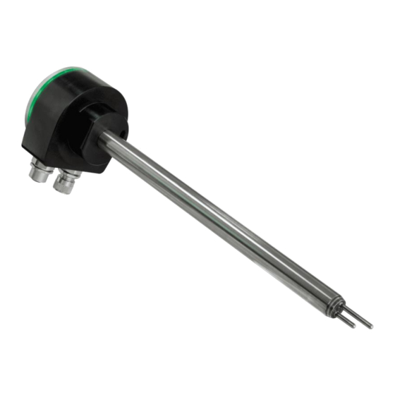
2 Application range ® The SCHMIDT Flow Sensor SS 20.700 (art. no.: 562 140) is designed for stationary measurement of the flow velocity as well as the temperature of air and gas with operating temperature from -20 … +120 °C and working pressure up to 16 bar. - Page 5 - Use clean and non-fluffy gloves or cloths or similar to handle the sensor. Version for “special gases” The version of the SS 20.700 for “special gases” receives a gas-specific adaption for the measurement of certain gases and gas mixtures.
-
Page 6: Mounting Instructions
Mounting method The sensor SS 20.700 can be mounted only by means of a compression fitting which supports the sensor tube and ensures frictional clamping. The compression fitting as well as a pressure protection kit is included in the scope of delivery. - Page 7 Correct measurements require a (laminar) flow, low in turbulence. The term “laminar” means here an air flow, low in turbulence (not according to its physical definition saying that the Reynolds number is < 2300). Instructions for Use – SCHMIDT ® Flow Sensor SS 20.700...
- Page 8 General installation conditions The sensor head of the SS 20.700 consists of two basic elements: Heater The longer of the two sensor tubes at the tip of the sensor head is the so-called heater. It consists of a heated, temperature-dependent resis- tor that is used to measure flow velocity.
- Page 9 E.g., honeycombs made of plastic or ceramics. Instructions for Use – SCHMIDT ® Flow Sensor SS 20.700 Page 9...
- Page 10 45 x D 5 x D Table 1 Run-in and run-out distances The profile factors specified in Table 2 may become void by the use of flow rectifiers. Instructions for Use – SCHMIDT ® Flow Sensor SS 20.700 Page 10...
- Page 11 2000 1983 99186 198372 595118 892677 1388609 2182100 Table 2 Profile factors and volume flows of different pipe diameters Both inner air friction and sensor locking are responsible. Instructions for Use – SCHMIDT ® Flow Sensor SS 20.700 Page 11...
- Page 12 Profile factor (for pipes with a circular cross-section) V Standard volume flow [m SCHMIDT Technology provides a "flow calculator" on its homepage for the calculation of flow velocity or volume flow in (circular) pipes or (rectan- gular) ducts for the different sensor types: www.schmidt-sensors.com...
- Page 13 Pipe profile factor V Standard volume flow [m Typical applications are: o Ventilation ducts o Exhaust air ducts The profile factors are equal for both cross-section forms. Instructions for Use – SCHMIDT ® Flow Sensor SS 20.700 Page 13...
- Page 14 Remove protective cap from sensor head. Carefully insert sensor into the duct of the compression fitting so that the end of the heater (longer tube) is positioned in the middle of the pipe. Instructions for Use – SCHMIDT ® Flow Sensor SS 20.700...
- Page 15 The sensor probe of the remote version is mounted with a compression fitting in the same way as the compact sensor. A wall mounting bracket is provided for fastening the sensor enclosure. Instructions for Use – SCHMIDT ® Flow Sensor SS 20.700...
- Page 16 Accessories ® The accessories required for mounting and operation of the SCHMIDT Flow Sensor SS 20.700 are listed in Table 3 below. Type / Art. no. Drawing Assembly Connecting cable - Threaded ring, knurl Standard with - Plug injection-moulded fixed length:...
-
Page 17: Electrical Connection
Electromechanical shielding Meshwork Table 4 ® The specified wire colors are valid when one of the SCHMIDT connecting cables is used (see subchapter Accessories, Table 3). Galvanically decoupled For cable with mat. no. 524942, the shield is not connected to the cable socket. - Page 18 Only expansion modules from SCHMIDT Technology may be connected to the module connector. Operating voltage The flow sensor SS 20.700 is protected against reverse polarity of the operating voltage. For its intended operation, it requires a DC voltage of 24 V with a tolerance of ±20 %.
- Page 19 For voltage mode, a measuring resistance of at least 10 kΩ is recommended. The maximum load capacitance C is 10 nF. Instructions for Use – SCHMIDT ® Flow Sensor SS 20.700 Page 19...
- Page 20 = 258 Ω. load is R L,min Here the excessive heating power of the load has to be considered. Overcurrent peaks are absorbed by the short circuit limiter. Instructions for Use – SCHMIDT ® Flow Sensor SS 20.700 Page 20...
- Page 21 (e.g. due to ESD or surge) of both polarities by means of a TVS diode. The output has no protective measures, exceeding the specified electrical operating values leads to irreversible damage. Transient Voltage Suppressor Diode, breakdown voltage approx. 30 V Instructions for Use – SCHMIDT ® Flow Sensor SS 20.700 Page 21...
-
Page 22: Signaling
LED bar (enclosure cover) ® The SCHMIDT Flow Sensor SS 20.700 has four Duo-LEDs (see Fig- ure 5-1) in the enclosure cover. They either indicate the flow velocity in fault-free operation in a quantitative way (bar graph mode) or they signal the cause of a problem (see Table 5). - Page 23 Flow sensor without auxiliary module In this case, the light ring signals the operating status of the SS 20.700, supplementary to the Duo-LED strip in the cover of the enclosure: ...
- Page 24 20 … 100 ms. Error signaling In current mode, the interface outputs 2 mA In voltage mode, the output switches to 0 V. In accordance with the Namur specification. Instructions for Use – SCHMIDT ® Flow Sensor SS 20.700 Page 24...
- Page 25 �� ∙ (�� − 4 ����) − 20 °�� �� ������,�� �� ������,�� 10 �� �� 16 ���� �� Table 9 Representation specification for measurement of medium temperature Instructions for Use – SCHMIDT ® Flow Sensor SS 20.700 Page 25...
- Page 26 11 V resp. 22 mA, in contrast to normal error signaling. This is to avoid a catastrophic feedback if a heating control uses the medium temperature sensor of the SS 20.700. The standard error signal (0 V or 2 mA) could be interpreted by the control as a very low temperature of the medium which would consequently lead to further heating.
- Page 27 The pulse outputs represent the flow velocity w as an alternative to the analog output. The basic version of the SS 20.700 maps the flow velocity w propor- tional to a frequency range [0 … f ] with selectable maximum fre- quency f (see Figure 5-4).
-
Page 28: Commissioning
Environmental condition Temperature ® The SCHMIDT Flow Sensor SS 20.700 monitors both the medium and the electronics temperature. As soon as one of the specified operating ranges is left, the sensor switches off both measuring functions associated with the medium and signals this error via the LED strip (according to Ta- ble 5) as via the light ring. -
Page 29: Service Information
Environmental conditions of medium ® The SCHMIDT Flow Sensor SS 20.700 is also suitable for relatively im- pure gases. Dust or non-abrasive particles can be tolerated as long as they do not form any deposits on the sensor elements. Deposits or other soiling must be detected during regular inspections and removed during cleaning because they can lead to distortion of the meas- urement result (see chapter 8 Service information). - Page 30 +U AGND Analog signal voltage per- Error signaling Eliminate errors manently at zero Short circuit against (A)GND Eliminate short circuit Table 10 Instructions for Use – SCHMIDT ® Flow Sensor SS 20.700 Page 30...
- Page 31 Every new sensor is accompanied by a certificate of compliance according to EN 10204-2.1. Material certificates are not available. Upon request, we shall prepare, at a charge, a factory calibration certifi- cate, traceable to national standards. Instructions for Use – SCHMIDT ® Flow Sensor SS 20.700 Page 31...
-
Page 32: Dimensions
9 Dimensions Compact sensor Figure 9-1 Remote sensor (including wall mounting bracket) Figure 9-2 Instructions for Use – SCHMIDT ® Flow Sensor SS 20.700 Page 32... -
Page 33: Technical Data
Stainless steel 1.4404 Sensor cable (remote sensor) Sheathing TPE, halogen-free Under reference conditions „o. m. v.“: of measured value; „o. f. v.“: of final value > 2 m/s) Instructions for Use – SCHMIDT ® Flow Sensor SS 20.700 Page 33... - Page 34 250 / 600 mm 1 … 10 m (steps: 1 m) - Remote sensor Cable: Weight Approx. 500 g max. (without connecting cable) Without signal current of pulse output 2 (relay) Instructions for Use – SCHMIDT ® Flow Sensor SS 20.700 Page 34...
-
Page 35: Declarations Of Conformity
11 Declarations of conformity SCHMIDT Technology GmbH herewith declares in its sole responsibility, that the product SCHMIDT Flow Sensor SS 20.700 Part-No. 562 140 is in compliance with the appropriate European guidelines and standards UK statutory requirements and designated standards. - Page 36 SCHMIDT Technology GmbH Feldbergstr. 1 78112 St. Georgen Germany Phone +49 (0)7724 / 899-0 +49 (0)7724 / 899-101 Email sensors@schmidttechnology.de www.schmidt-sensors.com www.schmidttechnology.de Instructions for Use – SCHMIDT ® Flow Sensor SS 20.700 Page 36...
Need help?
Do you have a question about the SS 20.700 and is the answer not in the manual?
Questions and answers