Table of Contents
Advertisement
Quick Links
Advertisement
Table of Contents

Subscribe to Our Youtube Channel
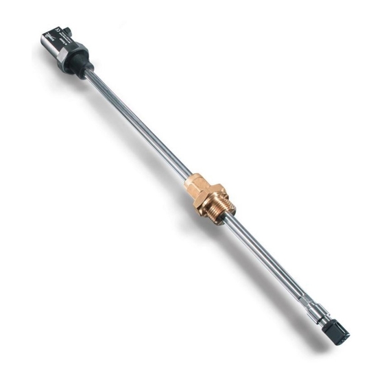
Summary of Contents for Schmidt SS 20.261
- Page 1 ® SCHMIDT Flow Sensor SS 20.261 Instructions for Use...
-
Page 2: Table Of Contents
Information concerning operation ..........15 Service information ................ 17 Technical data ................18 EC Declaration of conformity ............19 Imprint: Copyright 2012 SCHMIDT Technology GmbH All rights reserved Version 527254.02B Subject to modifications Instructions for Use SS 20.261 Page 2... -
Page 3: Important Information
2). In particular, it is not designed for direct or indirect personal protection. SCHMIDT Technology cannot give any warranty as to its suitability for a certain purpose and cannot be held liable for accidental or sequential damage in connection with the delivery, performance or use of this unit. -
Page 4: Application Range
Thus, the resulting output signal is independent from the pressure and temperature of the medium to be measured. The SS 20.261 is designed for the use inside closed rooms and is not suitable for outdoor use. Equates to the real flow velocity under standard conditions. -
Page 5: Mounting Instructions
3 Mounting instructions General information on handling The SS 20.261 is a precision instrument with high measuring sensitivity. In spite of the robust construction of the sensor tip soiling of the inner sensor elements can lead to distortion of measurement results (see also chapter 8 Service information). - Page 6 The sensor head must be located in the center of the pipe to obtain a correct measurement inside the pipe. In case of vertical downdraft and maximum overpressure of 8 bar. Measurement deviation < 1 % Instructions for Use SS 20.261 Page 6...
- Page 7 5 x D Two 90° bends in one plane (2-dimensional) Two 90° bends (3-dimensional change in direction) 35 x D 5 x D Shut-off valve 45 x D 5 x D Table 1 Instructions for Use SS 20.261 Page 7...
- Page 8 /h (see Table 2). SCHMIDT Technology provides a convenient calculation tool to compute flow velocity or volume flow in pipes for all its sensor types and measuring ranges. This “Flow Calculator” can be directly used on or downloaded from SCHMIDT homepage: http://www.schmidttechnology.de/de/sensorik/download/FlowCalculator.zip...
- Page 9 0.842 388.8 72.23 14,446 21,670 32,505 0.845 437.0 91.47 18,294 27,440 41,161 0.847 486.0 113.53 22,706 34,059 51,089 0.850 534.0 0.852 137.39 27,477 41,216 61,824 585.0 165.27 33,054 49,581 74,371 0.854 Table 3 Instructions for Use SS 20.261 Page 9...
- Page 10 Wrap thread using a common sealing tape, for example made of PTFE. Remove protective cap from sensor tip and push compression fitting up to the dead end of the sensor head. Instructions for Use SS 20.261 Page 10...
- Page 11 Make sure to close the safety chain before pressure is applied. The chain lock must be hung up in a way to avoid sagging of the chain. Figure 4: Safety chain Instructions for Use SS 20.261 Page 11...
-
Page 12: Electrical Connection
Only operate sensor within the defined range of operating voltage (24 V DC ± 10 %). Undervoltage may result in malfunction. Overvoltage may lead to irreversible damage to the sensor. Must be welded. Instructions for Use SS 20.261 Page 12... -
Page 13: Signalizations
Supply voltage too low Ready for operation Supply voltage too high Medium temperature beyond specification range Sensor defective LED off LED flashes (approx. 2 Hz): green LED on: green LED flashes (approx. 2 Hz): red Instructions for Use SS 20.261 Page 13... - Page 14 For a correct temperature measurement, the flow velocity on the sensor head must be > 2 m/s. An excessive temperature value is output if flow velocity is < 2 m/s. In accordance with NAMUR specification. Instructions for Use SS 20.261 Page 14...
-
Page 15: Startup
6 Startup ® Prior to switching on the SCHMIDT Flow sensor SS 20.261, the following checks have to be carried out: Immersion depth of the sensor probe and alignment of the housing Tightening of the fastening screw of the through-bolt joint, correct installation of safety chain ... - Page 16 Check the voltage supply fluctuating Mounting conditions: Check mounting conditions Sensor head is not in optimal position Run-in/run-out distance is too short Check operating parameters Strong fluctuations of pressure or temperature Table 6 Instructions for Use SS 20.261 Page 16...
-
Page 17: Service Information
Every new sensor is accompanied by a certificate of compliance according to EN10204-2.1. Material certificates are not available. Upon request, we shall prepare, at a charge, a factory calibration certificate, traceable to national standards. Instructions for Use SS 20.261 Page 17... -
Page 18: Technical Data
Table 7 Under alignment conditions and with regard to the reproducibility of the reference. Error messaging: 2 mA; exceeding measuring range: up to 22 mA With cable end sleeves **** According EN 50178 Instructions for Use SS 20.261 Page 18... -
Page 19: Ec Declaration Of Conformity
10 EC Declaration of conformity Instructions for Use SS 20.261 Page 19... - Page 20 SCHMIDT Technology GmbH Feldbergstrasse 1 78112 St. Georgen / Germany Phone +49 (0)7724 / 899-0 Fax +49 (0)7724 / 899-101 info@schmidttechnology.de www.schmidttechnology.de Instructions for Use SS 20.261 Page 20...


Need help?
Do you have a question about the SS 20.261 and is the answer not in the manual?
Questions and answers