KITO L5 Owner's Manual And Safety Instructions
Manually lever operated chain hoist
Hide thumbs
Also See for L5:
- Owner's manual and safety instructions (40 pages) ,
- Supplementary manual (7 pages) ,
- Supplementary manual (8 pages)
Table of Contents
Advertisement
Quick Links
OM-L5ZZZZ-KCE-03
Owner's (Operator's) Manual
and
Safety Instructions
Manually Lever Operated
Chain Hoist Model L5
WARNING
This equipment must not be installed, operated or
maintained by any person who has not read and
understood all the contents of this manual. Failure to read
and comply with the contents of this manual can result in
serious bodily harm or death, and/or property damage.
Advertisement
Table of Contents

Subscribe to Our Youtube Channel
Related Manuals for KITO L5


Summary of Contents for KITO L5
- Page 1 OM-L5ZZZZ-KCE-03 Owner’s (Operator’s) Manual Safety Instructions Manually Lever Operated Chain Hoist Model L5 WARNING This equipment must not be installed, operated or maintained by any person who has not read and understood all the contents of this manual. Failure to read and comply with the contents of this manual can result in serious bodily harm or death, and/or property damage.
- Page 2 Fill in the following product informaition for identification and future reference to avoid referring to the wrong manual for information or instructions on installation, operation, inspection, maintenance, or parts. Model Code: Serial Number: Date of Purchase: Dealer: Page 2 of 38...
-
Page 3: Table Of Contents
Table of Contents 1. IMPORTANT INFORMATION AND WARNINGS ..............4 1.1. R ................4 EGARDING NSTRUCTIONS ANUAL 1.2. P ......................4 ROHIBITED RACTICES 2. TECHNICAL INFORMATION ....................7 2.1. S ........................7 PECIFICATIONS 2.2. D ......................... 8 IMENSIONS 3. OPERATION ..........................9 3.1. -
Page 4: Important Information And Warnings
KITO will not be held liable for any malfunction, lack of performance or accident if the product is being used in conjunction with any other equipment. If the product is to be used for unintended purposes, please confirm with your dealer in advance. - Page 5 ◼ safety and operating instructions must be fully understood. WARNING FDDDDK ◼ Do NOT use a deformed or scarred hook. Replace components only with KITO approved parts. ◼ CAUTION FDDDDK Make sure that the nameplate is readable. ◼ Before operation, make sure to perform all inspections given in 4.1 Inspection ◼...
- Page 6 Do NOT use the ◼ ◼ Do NOT extend the hoist by stepping on lever by attaching a the lever. pipe to it. Do NOT swing a lifted load. ◼ Do NOT use the load chain as an earth for welding. ◼...
-
Page 7: Technical Information
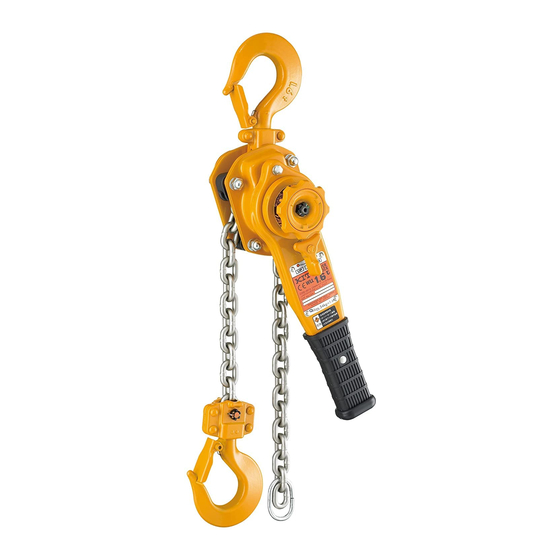
2. Technical Information 2.1. Specifications 2.1.1. Schematics Top hook Free chain knob Select lever Latch Nameplate Chain pin Anchor screw Lever Connection yoke Load chain Bottom hook Chain stopper link 2.1.2. Operating Conditions and Environment Temperature Range: -40° to +60°C (-40° to +140°F) Humidity: 100% or less, this is not an underwater device. -
Page 8: Dimensions
2.2. Dimensions 189.6000 216.6997 112.0000 Up to 3 tonnes 6 tonnes 189.6000 303.9029 112.0000 9 tonnes Table 2-2 Hoist Dimensions Units: mm Hoist Code LB008 23.5 35.5 LB015 42.5 LB025 36.5 LB030 24.5 LB060 LB090 72.5 41.5 Page 8 of 38... -
Page 9: Operation
3. Operation 3.1. Introduction Operating a heavy load may result in hazardous situations. Before operating, read and comply with all of the information in this clause and 1.2 Prohibited Practices. Before operating the hoist, secure the workplace as follows: - Ensure to arrange the workplace to work smoothly. - Ensure to keep a good view to monitor the operation, otherwise arrange watch personnel. -
Page 10: Load Signal (As Option)
3.3.2. How to Operate DANGER Do NOT operate the free chain knob in lifting or lowering. FDDDDK CAUTION Before operating, make sure that the hoist is out of the free chaining mode FDDDDK and the select lever position meets your operation demands. The following table shows select lever position and lever operation for lifting and lowering. - Page 11 3.4.2. How to Operate 1. Operate the hoist by holding the lever grip in the middle. 2. The following events of the load signal warn you of an overload. - The lever grip is bent. - The lever clicks. - The signal window changes from green to red. 3.
-
Page 12: Inspection
4. Inspection To maintain continuous and satisfactory operation, a regular inspection procedure must be initiated to replace worn or damaged parts before they become unsafe. 4.1. Inspection Classification Inspection intervals must be determined by the individual application and are based on the type of service to which the hoist will be subjected and the degree of exposure to wear, deterioration or malfunction of the critical components. -
Page 13: Daily Inspection
Evaluation and resolution of the results of the frequent inspections shall be made by a designated person so that the hoist is maintained in safe working condition. WARNING Do NOT use components beyond the stated criteria or KITO-unauthorized FDDDDK parts. - Page 14 In addition to the daily inspections, perform the following checks. Table 4-2 Frequent Inspection Methods and Criteria Item Method Criteria Action Put the hoist under a light load and check the following items of “Function - ……” Function – Set the select lever to ‘UP’ and Moving the lever forwards and Repair or replace as Lifting...
- Page 15 Item Method Criteria Action Hooks – Visual, Function - Should be held in place on the tip Replace hook Hook Latches of the hook. latch - Should move smoothly. WARNING Do NOT use FDDDDK the hook with the latch missing. Hooks –...
-
Page 16: Periodic Inspection
4.4. Periodic Inspection In addition to the frequent inspections, perform the following checks. Table 4-3 Periodic Inspection Methods and Criteria Item Method Criteria Action Chain Pin – Visual, Measure - Significantly deformed pin should Replace. Deformation be discarded. Chain Pin – - Should be free of scars or Replace. - Page 17 Item Method Criteria Action Braking System – Measure Should have uniform thickness of A Replace. Bushing Wear dimension. A dimension (mm) Capacity (tonnes) Standard Discard Braking System – Visual Should lubricated that Soak the bushing in Bushing Lubrication Heat with a match flame. lubricant oozes off the surface.
- Page 18 Item Method Criteria Action – Lifting system Visual Should be free of wear in the Replace Load Sheave pockets or scars on the rising parts. – Lifting system Visual Should not be chipped, unevenly Replace Cogs worn or scarred. – Lifting system Visual...
- Page 19 Item Method Criteria Action Body – Visual Should free major Replace. Frame A, B deformation or significant scars. Stay Bolts - Should be free of loose caulking. Top Pin Hole - Should be free of cracks on the Pawl Shafts welding parts.
- Page 20 Item Method Criteria Action Before reuse, reassemble properly the hoist in accordance with 0 Maintenance in this manual Preoperational and perform the following the checks. Checks Checks under No Function, Auditory - The lever should be operated Repair or replace as Load –...
-
Page 21: Maintenance
Do NOT extend the load chain, i.e. add extra links. Remove old grease from the disassembled parts. ◼ Replace components only with KITO approved parts. ◼ To reassemble, apply new grease, and use a new split pin and snap ring. -
Page 22: Components
4.8. Components Exclusive for 2 1/2 & 3 tonnes Fig. # Part # Part Name Fig. # Part # Part Name Fig. # Part # Part Name 1001 Top Hook Set 116 Load Sheave 223 Select-pawl Spring 1071 Latch Assembly 161 Chain Guide 5211 Lever Assembly 163 Top Pin... -
Page 23: Disassembly
4.9. Disassembly Proceed as follows: 4.9.1. Free Chain Knob 1) Pull out (50) Split Pin and remove (49) Slotted Nut. 2) Remove (48) Spring Holder, (47) Free Chain Spring, (45) Free Chain Knob Assembly, (43) Brake Spring and (44) Cam Guide from (16) Pinion. 4.9.2. - Page 24 WARNING Do NOT apply oil to the friction side of the female FDDDDK thread. CAUTION Ensure to clean the friction side of the female FDDDDK thread. Figure 5-2 Lever Assembly Refer to Figure 5-2, proceed as follows: 1) Apply (G3) grease lightly to the thread of (33) Female Thread. 2) Attach the friction side of (33) Female Thread to (29) Brake Cover Assembly and set (37) Lever Assembly on them.
- Page 25 1) Set (52) Load Chain to (19) Load Sheave as Frame top: Flat Stay bolt shown in Figure 5-6, and attach (20) Chain Top pin hole Guide and (21) Stripper. Refer to Figure 5-6. Welding part CAUTION FDDDDK Keep (53) Chain stopper link in parallel with ◼...
- Page 26 4.10.6. Gears Refer to Figure 5-10, proceed as follows: 1) For capacity of 2 1/2 tonnes or more, attach (18) Load Gear to the serration part of (19) Load Sheave. Note: Make sure that the load sheave is inserted to the load gear completely.
- Page 27 4.10.8. Lever & Body 1) Attach the lever assembled in 4.10.1 to the previously-assembled bake. Ensure to fit the rims of (10) Frame A assembly and (29) Brake Cover Assembly in right direction. 2) Fit (29) Brake Cover Assembly and (10) Frame A Assembly by screwing (33) Female Thread of the lever assembly clockwise to the thread of (16) Pinion until making clicking sounds.
-
Page 28: Preoperational Checks
6) Set (43) Brake Spring (silver color) into the slot of the back of (45) Free Chain Knob Assembly. Slot for spring Note: As shown in Figure 5-14, set the end of the spring to the rib of the knob. Slot for cam guide Back of (45) free Set end of spring... -
Page 29: Troubleshooting
If a defect is found in the hoist, stop using it immediately and check for the cause of the defect. ◼ Ensure that competent people conduct repairs, otherwise please contact your dealer. ◼ Replace components only with KITO approved parts. ◼ Symptom Cause Remedy 1)... - Page 30 Symptom Cause Remedy Hoist will lift Poor pawl movement caused by faulty pawl Perform periodic overhauls. intermittently spring -The spring is loose or damaged. -Slight irregular Mis-assembly of pawl spring Reassemble it properly and ensure to clicking check clicking sound of the pawl before reuse.
- Page 31 Symptom Cause Remedy Load drifts or slips Mis-assembly of friction plates, i.e. friction Reassemble it properly as shown in the when lowering starts. plates at the same side as shown or one following picture and ensure to check hoist lost functions before reuse.
- Page 32 Symptom Cause Remedy 4) Load chain CAUTION -The load chain is one of the most critical parts of the hoist. Ensure to maintain the chain carefully including proper FDDDDK handling, good maintenace and inspection. -Replace a chain pin when the load chain is replalced. Load chain wear Lack of lubricant Keep the load chain lubricated.
- Page 33 Symptom Cause Remedy 5) Hooks CAUTION To prevent the hooks from being damaged, handle them properly in accordance with this manual. FDDDDK Stretched hook Overload WARNING Stretched hook -Hook will begin to deform gradually under a load over the double rated capacity. warns you about overload.
-
Page 34: Warranty
KITO warrants that KITO’s Products, when shipped, shall be free from defects in workmanship and/or materials under normal use and service and KITO shall, at the election of KITO, repair or replace free of charge any parts or items which are proven to have said defects, provided that all claims for defects under this warranty shall be made in writing immediately upon discovery and, if there is anything within one(1) year from the date of purchase of KITO’s Products by Purchaser and provided,... -
Page 35: Repair Part List
7. Repair Part List 7.1. Up to 3 tonnes Exclusive for 2 1/2 & 3 tonnes Capacity Parts Fig. # Part # Part Name (tonnes) Hoist 1 1/2 2 1/2 1001 Top Hook Set L5BC008-1001 L5BC015-1001 L5BA025-1001 L5BC030-1001 1071 Latch Assembly L5BA008-1071 L5BA016-1071 L5BA025-1071... -
Page 36: Exclusive Parts
7.2. Exclusive Parts 6 tonnes 9 tonnes Note: These basic bodies are the same as 3 tonnes. Parts Capacity Fig. # Part # Part Name (tonnes) Hoist 1001 Top Hook Set L5BC060-1001 L5BC090-1001 2001 Hook Assembly L5BC090-2001 1071 Latch Assembly L5BA063-1071 L5BA090-1071 2011 Top Hook Yoke A &... -
Page 37: Optional Parts
7.3. Optional Parts Lever assembly for load signal type ① ② ③ ④ ⑤ Capacity Parts (tonnes) Fig.# Part# Part Name Hoist 1 1/2 2 1/2 5211 Lever Set Y3SC008-5211 Y3SC015-5211 Y3SC025-5211 Y3SC030-5211 Y3SC060-5211 Y3SC090-5211 Lever 6211 Y3SC008-6211 Y3SC015-6211 Y3SE025-6211 Y3SC030-6211 Assembly Name Plate...
Need help?
Do you have a question about the L5 and is the answer not in the manual?
Questions and answers