Advertisement
Quick Links
www.ti.com
Design Guide: TIDA-010243
Cost-Effective, 3-Phase CT Electricity Meter Reference
Design Using Standalone ADC
Description
This reference design implements Class 0.1
three-phase energy measurement using a high-
performance, multichannel analog-to-digital converter
(ADC), which samples current transformers (CT)
at 8 kHz to measure the current and voltage of
each leg of the AC mains. The reference design
achieves high accuracy across a wide input current
range (0.01 A – 100 A) and supports high sampling
frequencies necessary for power quality features such
as individual harmonic analysis. An ADC sample
rate of 32 kSPS can be achieved when using a TI
Arm
®
Cortex
®
-M0+ host microcontroller for metrology.
The necessary software functionality is implemented
by porting the
ADC Energy Metrology
MSPM0G3507 and can be compiled with Code
™
Composer Studio
.
Resources
TIDA-010243
MSPM0G3507,
ADS131M08
THVD1400, TRS3232E,
TPS3840
TMAG5273, ISO6731,
ISO6720
Ask our TI E2E
Load
Phase A
Phase B
ADS131M08
Phase C
VDD
GND
Voltage C
ADC
¡
Current A
CT #1
ADC
¢ £
Voltage C
ADC
¤ ¥
Current A
CT #2
ADC
CSn
SCLK
Voltage C
DIN
¦ §
ADC
DOUT
Control +
Serial
RESET
Current C
Interface
ADC
¨ ©
DRDY
CT #3
CLKIN
ADC
ADC
Source from Utility
TIDUF25 – JUNE 2023
Submit Document Feedback
library to
Design Folder
Product Folder
Product Folder
Product Folder
™
support experts
VCC
DVCC
GND
DVSS
10980.4 kWh
VCC
UART1 TX
MSP430
TPS3840
UART1 RX
FR4131
RST/NMI
RESET
CT
GND
GND
Button
Button
1
2
ACT
ISO-ACT
MSPM0G1107
ISO6720
REACT
ISO-REACT
GPIO
SPI CLK
SPI PICO
VCC
RS232_VCC
DTR
SPI POCI
GND
RS232_GND
TPS709
RTS
RGND
Interruptible GPIO
ISO6731
UART2 TX
TRS3232E
ADC_CLKIN
UART2 RX
CLKOUT
GPIO
GND
GPIO
HFXIN
RE
16.384
MHz XTAL
Board Header to
RGND
HFXOUT
WE
UART3 TX
External Radio/
THVD1400
VCC3
Radio Module
UART3 RX
Copyright © 2023 Texas Instruments Incorporated
Features
•
3-phase metrology for electricity meters that meets
ANSI C12.20 Class 0.1 active energy accuracy
requirements across 2000:1 input range
•
Active and reactive energy and power, root mean
square (RMS) current and voltage, power factor,
and line-frequency calculations
•
Isolated RS-232 and RS-485 with 5-kV
isolation
•
Tested across 10 mA to 100 A and 9-V to 270-V
input range
•
Software for energy metrology and displaying
results on a Microsoft
Applications
•
Electricity meter
•
Power quality meter
•
Power quality analyzer
RS-232
Connection
RS-485
Connection
Cost-Effective, 3-Phase CT Electricity Meter Reference Design Using
Description
RMS
®
Windows
®
PC GUI
Standalone ADC
1
Advertisement

Related Manuals for Texas Instruments TIDA-010243


Summary of Contents for Texas Instruments TIDA-010243
- Page 1 RGND HFXOUT UART3 TX External Radio/ RS-485 THVD1400 VCC3 Radio Module UART3 RX Connection Source from Utility TIDUF25 – JUNE 2023 Cost-Effective, 3-Phase CT Electricity Meter Reference Design Using Submit Document Feedback Standalone ADC Copyright © 2023 Texas Instruments Incorporated...
-
Page 2: System Description
• Per-phase current THD • Voltage phase-to-phase angle • Per-phase zero crossing TIDA-010243 is a Class 0.1 high-accuracy 3-phase CT electricity meter reference design, using a single 8-channel standalone ADS131M08 ADC and cost-effective MSPM0G3507 MCU. The reference design can also be used for energy metering in popular products such as Level 2 EV chargers and AC wallboxes. - Page 3 Measured parameters • Power factor • Line frequency Update rate for measured parameters Approximately equal to 1 second TIDUF25 – JUNE 2023 Cost-Effective, 3-Phase CT Electricity Meter Reference Design Using Submit Document Feedback Standalone ADC Copyright © 2023 Texas Instruments Incorporated...
- Page 4 (3 phases) and the current thru the N (neutral) wire. In the TIDA-010243 block diagram, a current transformer (CT) connects to each current channel and a simple voltage divider is used for dividing down the corresponding voltage of each channel. Each CT has an associated burden resistor that must be connected at all times to protect the measuring device.
- Page 5 Connection Source from Utility Figure 2-1. TIDA-010243 Block Diagram, Three-Phase + Neutral Configuration By reducing the voltage fed to the three ADS131M08 voltage ADC channels, voltage to current crosstalk, which actually affects metrology accuracy more than voltage ADC accuracy, is reduced at the cost of voltage accuracy, thereby resulting in more accurate energy measurements at lower currents.
- Page 6 The Cost-Effective, 3-Phase CT Electricity Meter Reference Design Using TIDUF25 – JUNE 2023 Standalone ADC Submit Document Feedback Copyright © 2023 Texas Instruments Incorporated...
- Page 7 AC magnets than a low-sample rate Hall switch. TIDUF25 – JUNE 2023 Cost-Effective, 3-Phase CT Electricity Meter Reference Design Using Submit Document Feedback Standalone ADC Copyright © 2023 Texas Instruments Incorporated...
- Page 8 ±1.2-V input voltage that can be sensed by the ADS131M08 device for the selected PGA gain value of 1 that is used for the voltage channels. Cost-Effective, 3-Phase CT Electricity Meter Reference Design Using TIDUF25 – JUNE 2023 Standalone ADC Submit Document Feedback Copyright © 2023 Texas Instruments Incorporated...
- Page 9 PGA gain of 1 that is used for the current channels. TIDUF25 – JUNE 2023 Cost-Effective, 3-Phase CT Electricity Meter Reference Design Using Submit Document Feedback Standalone ADC Copyright © 2023 Texas Instruments Incorporated...
- Page 10 Energy Calculations are the Real Time Clock (RTC) with calendar function, CRC-16 or CRC-32 HW module, four Universal Asynchronous Receiver Transmitters (UARTs), two I2Cs with 1Mbps and up to 60 GPIOs. Cost-Effective, 3-Phase CT Electricity Meter Reference Design Using TIDUF25 – JUNE 2023 Standalone ADC Submit Document Feedback Copyright © 2023 Texas Instruments Incorporated...
- Page 11 The CRC16 module of the MSPM0+ MCU is also used to accelerate the CRC calculations that are done to verify the integrity of the ADC packet sent by the ADS131M08 device. TIDUF25 – JUNE 2023 Cost-Effective, 3-Phase CT Electricity Meter Reference Design Using Submit Document Feedback Standalone ADC Copyright © 2023 Texas Instruments Incorporated...
- Page 12 This device is specifically used in this design to convert from UART to RS-485 signals. Cost-Effective, 3-Phase CT Electricity Meter Reference Design Using TIDUF25 – JUNE 2023 Standalone ADC Submit Document Feedback Copyright © 2023 Texas Instruments Incorporated...
- Page 13 This chip supports a signaling rate of 50Mbps and operates from a 1.71-V to 1.89-V and 2.25-V to 5.5-V supply in the temperature range: –40°C to +125°C. TIDUF25 – JUNE 2023 Cost-Effective, 3-Phase CT Electricity Meter Reference Design Using Submit Document Feedback Standalone ADC Copyright © 2023 Texas Instruments Incorporated...
- Page 14 These regulators can be put into shutdown mode by pulling the EN pin low. The shutdown current in this mode goes down to 150 nA (typical). Cost-Effective, 3-Phase CT Electricity Meter Reference Design Using TIDUF25 – JUNE 2023 Standalone ADC Submit Document Feedback Copyright © 2023 Texas Instruments Incorporated...
- Page 15 Figure 2-7 shows how the TMAG5273 defines the X, Y, and Z directions: Figure 2-7. Field Direction Definition TIDUF25 – JUNE 2023 Cost-Effective, 3-Phase CT Electricity Meter Reference Design Using Submit Document Feedback Standalone ADC Copyright © 2023 Texas Instruments Incorporated...
- Page 16 The external 16.384-MHz crystal is divided by 2 to create the 8.192-MHz output frequency for CLK_OUT. An internal 32.768-kHz LFOSC is used as the clock source for the auxiliary clock (RTCCLK) of the device. All these settings are configured in the TIDA-010243.syscfg file in the software deliverable, utilizing the graphical Clock Tree configuration inside the SYSCONFIG tool.
-
Page 17: Direct Memory Access (Dma)
0 for each channel (note that software phase compensation is used instead of ADS131M08 hardware phase compensation). TIDUF25 – JUNE 2023 Cost-Effective, 3-Phase CT Electricity Meter Reference Design Using Submit Document Feedback Standalone ADC Copyright © 2023 Texas Instruments Incorporated... - Page 18 The foreground process includes the initial setup of the MSPM0+ MCU hardware and software and the ADS131M08 registers immediately after a device RESET. Figure 3-2 shows the flowchart for this process. Cost-Effective, 3-Phase CT Electricity Meter Reference Design Using TIDUF25 – JUNE 2023 Standalone ADC Submit Document Feedback Copyright © 2023 Texas Instruments Incorporated...
- Page 19 , active power, and reactive power. These dot products are used by the foreground process to calculate the corresponding metrology readings in real-world units. Processed TIDUF25 – JUNE 2023 Cost-Effective, 3-Phase CT Electricity Meter Reference Design Using Submit Document Feedback Standalone ADC Copyright © 2023 Texas Instruments Incorporated...
- Page 20 = Offset used to subtract effects of crosstalk on the active power measurements from other ACT_offset,ph phases and the neutral Cost-Effective, 3-Phase CT Electricity Meter Reference Design Using TIDUF25 – JUNE 2023 Standalone ADC Submit Document Feedback Copyright © 2023 Texas Instruments Incorporated...
- Page 21 7. App. import energy (apparent energy when active energy ≥ 0) 8. App. export energy (apparent energy when active energy < 0) TIDUF25 – JUNE 2023 Cost-Effective, 3-Phase CT Electricity Meter Reference Design Using Submit Document Feedback Standalone ADC Copyright © 2023 Texas Instruments Incorporated...
- Page 22 MSPM0+ MCU, which triggers the Port ISR, and the background process is run within the Port ISR. Figure 3-4 shows the background process, which mainly deals with timing-critical events in the test software. Cost-Effective, 3-Phase CT Electricity Meter Reference Design Using TIDUF25 – JUNE 2023 Standalone ADC Submit Document Feedback Copyright © 2023 Texas Instruments Incorporated...
- Page 23 ADS131M08 or read any registers during typical ADC sample readouts, a NULL command is sent to the ADS131M08, which allows the designer to get the ADC samples from the ADS131M08 without changing the TIDUF25 – JUNE 2023 Cost-Effective, 3-Phase CT Electricity Meter Reference Design Using Submit Document Feedback Standalone ADC Copyright © 2023 Texas Instruments Incorporated...
- Page 24 Once the per_sample_energy_pulse_processing is completed, the test software exits from the port ISR. Cost-Effective, 3-Phase CT Electricity Meter Reference Design Using TIDUF25 – JUNE 2023 Standalone ADC Submit Document Feedback Copyright © 2023 Texas Instruments Incorporated...
- Page 25 This estimate is then subtracted from each voltage and current raw ADC sample. TIDUF25 – JUNE 2023 Cost-Effective, 3-Phase CT Electricity Meter Reference Design Using Submit Document Feedback Standalone ADC Copyright © 2023 Texas Instruments Incorporated...
- Page 26 Because the average power tends to be a stable value, this way of generating energy pulses is very steady and free of jitter. Cost-Effective, 3-Phase CT Electricity Meter Reference Design Using TIDUF25 – JUNE 2023 Standalone ADC Submit Document Feedback Copyright © 2023 Texas Instruments Incorporated...
-
Page 27: Phase Compensation
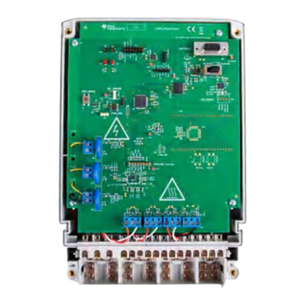
ADS131M08 device. If this hardware phase compensation scheme is used, filter coefficients are not necessary so it is not necessary to divide by the gain of the filter coefficients. TIDUF25 – JUNE 2023 Cost-Effective, 3-Phase CT Electricity Meter Reference Design Using Submit Document Feedback Standalone ADC Copyright © 2023 Texas Instruments Incorporated... - Page 28 Figure 4-1 shows the location of various pieces of the reference design based on functionality. Figure 4-1. Top View of TIDA-010243 Design With Components Highlighted 4.1.2 Cautions and Warnings At high currents, the terminal block can get warm. In addition, note that the phase voltages are fed to the board so take the proper precautions.
-
Page 29: Test Setup
4.2 Test Setup 4.2.1 Connecting the TIDA-010243 to the Metering Test Equipment The design has support for 3-phase + Neutral configuration with current transformers (CT). AC voltages and currents can be applied to the board for testing purposes at these points: •... - Page 30 (WARNING) isolated, do not connect to this header when running off Mains and Mains is not isolated. Cost-Effective, 3-Phase CT Electricity Meter Reference Design Using Standalone ADC TIDUF25 – JUNE 2023 Submit Document Feedback Copyright © 2023 Texas Instruments Incorporated...
- Page 31 BSL_invoke line on Was used on 1st silicon revision, not needed anymore. VDD_3V3 or GND respectively. MSPM0G3507 TIDUF25 – JUNE 2023 Cost-Effective, 3-Phase CT Electricity Meter Reference Design Using Standalone ADC Submit Document Feedback Copyright © 2023 Texas Instruments Incorporated...
- Page 32 (2) text to denote which parameter is being displayed, and (3) the actual value of Cost-Effective, 3-Phase CT Electricity Meter Reference Design Using TIDUF25 – JUNE 2023 Standalone ADC Submit Document Feedback Copyright © 2023 Texas Instruments Incorporated...
- Page 33 Click the green button to view the results. TIDUF25 – JUNE 2023 Cost-Effective, 3-Phase CT Electricity Meter Reference Design Using Submit Document Feedback Standalone ADC Copyright © 2023 Texas Instruments Incorporated...
- Page 34 After the user clicks this button, the Meter events and consumption window pops up, as Figure 4-7 shows. Cost-Effective, 3-Phase CT Electricity Meter Reference Design Using TIDUF25 – JUNE 2023 Standalone ADC Submit Document Feedback Copyright © 2023 Texas Instruments Incorporated...
- Page 35 In addition, all 5 FLASH access routines must be placed into the RAM area because when calibration takes place, multiple read and write operations to the last FLASH sector are executed. TIDUF25 – JUNE 2023 Cost-Effective, 3-Phase CT Electricity Meter Reference Design Using Submit Document Feedback Standalone ADC Copyright © 2023 Texas Instruments Incorporated...
- Page 36 TI meter observed • value is the calibration point configured in the AC test source desired Cost-Effective, 3-Phase CT Electricity Meter Reference Design Using TIDUF25 – JUNE 2023 Standalone ADC Submit Document Feedback Copyright © 2023 Texas Instruments Incorporated...
- Page 37 3. Modify only the phase-shift to a non-zero value; typically, +60° is chosen. The reference meter now displays a different % error for active power measurement. This value can be negative. TIDUF25 – JUNE 2023 Cost-Effective, 3-Phase CT Electricity Meter Reference Design Using Submit Document Feedback Standalone ADC Copyright © 2023 Texas Instruments Incorporated...
- Page 38 Figure 4-9. Calibration Factors Window Cost-Effective, 3-Phase CT Electricity Meter Reference Design Using TIDUF25 – JUNE 2023 Standalone ADC Submit Document Feedback Copyright © 2023 Texas Instruments Incorporated...
-
Page 39: Test Results
1.85 1.82 Hysteresis Voltage, Vhys = VIT+ - VIT– 1.85 1.82 –1.74 = 0.11 –1.72 = 0.10 TIDUF25 – JUNE 2023 Cost-Effective, 3-Phase CT Electricity Meter Reference Design Using Submit Document Feedback Standalone ADC Copyright © 2023 Texas Instruments Incorporated... - Page 40 The "% Error" columns in the following 6 tables and plots are calculated as the difference between the multiple reference input values to TIDA-010243 and the measured values, shown on the PC GUI. The reference input values to TIDA-010243 are generated by a PTS3.3C Source Generator/Reference Meter from the company...
- Page 41 -0.3 -0.5 -0.7 Current (A) Figure 4-12. Phase A RMS Current % Error Versus Current, 3-Phase Mode TIDUF25 – JUNE 2023 Cost-Effective, 3-Phase CT Electricity Meter Reference Design Using Submit Document Feedback Standalone ADC Copyright © 2023 Texas Instruments Incorporated...
- Page 42 -0.1 -0.15 -0.2 Voltage (V) Figure 4-13. Phase B RMS Voltage % Error Versus Voltage, 3-Phase Mode Cost-Effective, 3-Phase CT Electricity Meter Reference Design Using TIDUF25 – JUNE 2023 Standalone ADC Submit Document Feedback Copyright © 2023 Texas Instruments Incorporated...
- Page 43 -0.3 -0.5 -0.7 Current (A) Figure 4-14. Phase B RMS Current % Error Versus Current, 3-Phase Mode TIDUF25 – JUNE 2023 Cost-Effective, 3-Phase CT Electricity Meter Reference Design Using Submit Document Feedback Standalone ADC Copyright © 2023 Texas Instruments Incorporated...
- Page 44 -0.1 -0.15 -0.2 Voltage (V) Figure 4-15. Phase C RMS Voltage % Error Versus Voltage, 3-Phase Mode Cost-Effective, 3-Phase CT Electricity Meter Reference Design Using TIDUF25 – JUNE 2023 Standalone ADC Submit Document Feedback Copyright © 2023 Texas Instruments Incorporated...
- Page 45 -0.3 -0.5 -0.7 Current (A) Figure 4-16. Phase C RMS Current % Error Versus Current, 3-Phase Mode TIDUF25 – JUNE 2023 Cost-Effective, 3-Phase CT Electricity Meter Reference Design Using Submit Document Feedback Standalone ADC Copyright © 2023 Texas Instruments Incorporated...
- Page 46 5.1.1 Schematics To download the schematics, see the design files at TIDA-010243. 5.1.2 BOM To download the bill of materials (BOM), see the design files at TIDA-010243. 5.1.3 PCB Layout Recommendations For this design, the following general guidelines must be followed: •...
-
Page 47: Documentation Support
Design and Documentation Support Software TIDA-010243 Energy Library Source code of Energy Library for TIDA-010243 5.3 Documentation Support 1. Texas Instruments, ADS131M08 8-Channel, Simultaneously-Sampling, 24-Bit, Delta-Sigma ADC Data Sheet 2. Texas Instruments, MSPM0G110x Mixed-Signal Microcontrollers Data Sheet 3. Texas Instruments,... - Page 48 TI products. TI’s provision of these resources does not expand or otherwise alter TI’s applicable warranties or warranty disclaimers for TI products. TI objects to and rejects any additional or different terms you may have proposed. IMPORTANT NOTICE Mailing Address: Texas Instruments, Post Office Box 655303, Dallas, Texas 75265 Copyright © 2023, Texas Instruments Incorporated...
Need help?
Do you have a question about the TIDA-010243 and is the answer not in the manual?
Questions and answers