
Subscribe to Our Youtube Channel
Related Manuals for HWM Pegasus Plus


Summary of Contents for HWM Pegasus Plus
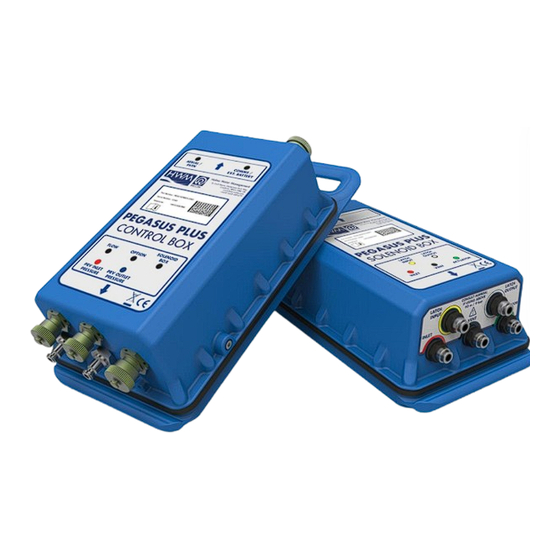
- Page 1 Pegasus Plus User Manual Version 1.4 Warning: This manual contains important safety and operating information. Please read, understand and follow the instructions in the manual.
-
Page 2: Table Of Contents
Hydraulics - Actuator MAINTENANCE Electronic controller Hydraulic Components of the PRV INSTALLATION SET Installation Details "Pegasus Plus" Intallation using Latch Solenoid for “Latch on Low Unreachable” Intallation using Latch Solenoid for “Latch on High Unreachable” AUTOCALL APPENDIX A - EXAMPLES... -
Page 3: Weee And The Battery Directive
HWM-Water products supplied after 13th August 2005 can be identified by the following symbol: Under HWM-Water Ltd’s Terms and Conditions of Sale, customers are responsible for the cost of returning WEEE to HWM-Water Ltd and we are responsible for the costs of recycling and reporting on that waste. Instructions for returning WEEE: Ensure that the WEEE meets one of the two conditions above. -
Page 4: Basic Configuration
Basic Configuration The first time Radwin is used the System Configuration window will appear automatically, it can also be accessed from “Configuration” in any of the Radwin Modules. In the “Database” tab you can set the folder where you will store all data received, by default this is C:\Radwin\Data. - Page 5 In this example the flow units are configured to Litres/sec. The logger type that appears by default can be configured in the “Logger Lists” tab. Which logger types appear in the drop down list can also be configured.
-
Page 6: Communications Configuration
Communications Configuration To configure the port for local communication, click on the tab “Manual Call” and for “Direct Cable Port” choose the correct port that the communications cable is connected to. If you intend to use a GSM modem to communicate with the logger during a power window then “Modem Port”... - Page 7 Choose a communications port number that is not in use for another application. To do this, double click on the port and in the new window that appears check "Enable Port ". To direct data to HWM Datagate, select “Datagate”, and enter “username” and “password” in the boxes below.
-
Page 8: Logger Configuration
“Radcom View”. Select “Dwonload Options” then “Advanced Download/Upload/Utilities” Note - It is not possible to configure the Pegasus Plus PRV controller using the Configure Logger Wizard, but if you prefer the Logging/GPRS elements can be configured using the wizard... - Page 9 Next is to set the logger type “Pegasus Plus (PRV Controller)” the speed of communication (Baud:) will automatically be set to 19200 and “Connection:” should be “Direct (cable)”. “Download Parameter Settings for Last Recording” should also be selected. Having made the above changes click on the OK button to start the communication with the logger.
-
Page 10: Select Communication
Select Communication Click on “GPRS Configuration” To send data to Datagate “GPRS UDP” should be selected, alarms can be sent directly by SMS, or by through Datagate (GPRS UDP), where they would be forwarded by email, or SMS(UK Only). SMS backup can only be used either directly to Datagate (+447786200833) or if an SMS modem is also available on the central computer. - Page 11 “Call Frequency” allows data to be sent at a specific interval. “Dual Call Frequency” allows different call frequency for “day” and “night” “Dual Alarm” Allows call frequency to be increased when and alarm condition occurs. The APN of the celluallar network provider can be entered if known, or GPRS Test can be used to identify it, later, click “Select..”...
-
Page 12: Configuration Phone Number
Configuration Phone Number At this point we set up the phone number from the SIM card, which is in the Pegasus Plus Configuring Input Channels When using either Contact Closure or Open Collector pulse devices “Power Save” should be used. - Page 13 This window configures the start time of the recording the time you see here is the previous start time, as long as this is in the past, the logging will automatically start at the next sample period. “Record” should always be cyclic, and stop disabled. All available channels should Enabled in “Logging mode”...
-
Page 14: Setting The Controller
Setting the controller The Pegasus Plus can be set to control by “Time”, “Flow” or both. In the event of contradiction the highest pressure is always used Flow Control In the tab "Flow Control" in the section "Flow Control" enter the “Sample Rate” and flow averaging Factor. - Page 15 Time Control In the tab "Time Control" can establish a table of values in which for at a certain time, a certain pressure is established. In the first section you can set the date time change for summer and winter. To modify or add hours change right position is selected and click on "Edit".
- Page 16 In the tab "Secondary Time Control” a Radcom hydro switch can be used to switch between the Main and Bypass PRV. This is to prevent the bypass valve seizing. Here we work with two states A and B are the states of the Hydro Switch To use this feature first “Enable Time Control Table”...
- Page 17 In the tab "Manual Override" you can set a time period in "Override Duration (hh: mm: ss)" in which the downstream pressure will keep the pressure is set to "Override Pressure". Once this time has elapsed, the controller will return to the Control Pegasus automatically. To reach this value can be done by two methods: Normal or fast...
- Page 18 In "Control Status" you can see if the controller is enabled and disabled. Also you can see what the "Target Pressure" and "Current Pressure" downstream were when Pegasus Plus was downloaded. The "Dead Band" can set the tolerance with which the driver must follow the target pressure.
- Page 19 Once the configuration is complete, click “Save” to save logger configuration to the computer, then click upload to programme the logger, Click on “Advanced…” and select the tick boxes as below If required “Secondary Time Parameters” can also be ticked. Override Parameters should only be selected on it’s own, once the controller is in an “Active”...
- Page 20 We can see a drop-down appears with loggers (Zone/Locations) that exist in the database. Right click on the Pegasus Plus created, and select “Location Database / Edit Location” to see the configuration. The most important tabs are Logger, Transducer, Units/Levels, Logger Call Numbers/Times and Logger Power Windows.
-
Page 21: Features Controllers Pressure Reducing Valves
Features controllers Pressure Reducing Valves Control by Pressure profile or flow Built-in data logger Battery life up to 5 years Compact design with IP68 protection Intelligent Operation "failure mode" Manual Override Option Specifications PRV Controllers INPUTS The "Pegasus"... - Page 22 DATA LOGGER Very resistant housing, IP68 protection, replaceable battery Battery life at least five years in normal operating conditions Record modes by Count and Event Compatible with standard software for Windows Radlog Logging interval: 1 second to 1 hour ...
-
Page 23: Installation Procedure
Installation Procedure The following assumes that the valve is not vented to the maximum or used to cut the water supply. The output pressure is not regulated during installation, and variations in inlet pressure affect the output pressure until the installation is complete. Ensure that the valve is working properly before connecting to the actuator, if not, it is essential to repair the PRV control before. - Page 24 The hydraulic system is now complete for the PRV 12. Connect the pressure sensors between the controller and quick-connects upstream and downstream. 13. Connect the controller to the solenoid box using the 6-pin military connector.
- Page 25 14. (Where necessary) - Connect the controller to the flow meter through the 4-pin military connector. 15. Connect the antenna to the FME connector and place it in the position to obtain better coverage. The electrical system is now installed PRV...
- Page 26 Verification of the configuration. It is recommended to download Parameter Settings again to check the configuration. We will check that has been configured correctly the new identity, GPRS Configuration (phone and time sent), the times and dates of recordecording start are correct and finally, that in “Status”...
- Page 27 General Notes a) No need to remove the original pilot PRV during system installation. b) The needle valve may need adjustment. c) Keep plastic pipes as short as practical, the shorter Best (Maximum of 1 meter).4 d) Do not extend connection cables (If done, the controller may not work properly). e) Protect plastic pipework from freezing using foam pipe insulation...
-
Page 28: General System Pressure Regulating
General System Pressure Regulating Introduction The actuator (hydraulic device supplied with the system) replaces the screw on the pilot of the PRV, a moving rod is used to control the maximum and minimum pressures. Working operation of the pilot remains unchanged, the only difference is that the pressure exerted on the inner spring will vary according to the instructions of the controller. -
Page 29: Maintenance
If any other problem occurs, the logger should be returned to "HWM-Water Ltd", for repair. The controller is designed for continuous operation over the life of the batteries. You do not need any maintenance. -
Page 30: Installation Set
Installation set Installation Details "Pegasus Plus" "Pegasus" PRV (Kit "A") - modulated pressure control... -
Page 31: Intallation Using Latch Solenoid For "Latch On Low Unreachable
Installation using Latch Solenoid for “Latch on Low Unreachable”... - Page 32 Installation using Latch Solenoid for “Latch on High Unreachable”...
-
Page 33: Autocall
AutoCall At this time we have prepared the Pegasus and database for data reception. The last step that remains is to open the Automatic Download module that is to be responsible for the receipt and processing of data. From any Radwin module go to the Start menu and click on Automatic Download. At this time we will see a window in which ports are checked data reception. -
Page 34: Appendix A - Examples
APPENDIX A - Examples Graphics Example of Reducing Time control - Two pressure points Night-time pressure has been significantly reduced, consequently the water losses due to leaks have also been reduced. During the day it is restored pressure to meet the daytime demand. - Page 35 Control-Flow - Two pressures...
-
Page 36: Appendix B - Flow Connection
APPENDIX B – FLOW CONNECTION... -
Page 37: Appendix C - Manual Communication
It is possible to communicate with the logger either by GPRS through Datagate, or directly by GSM with GSM Modem. Parameters uploaded by GPRS will be collected from Datagate when the Pegasus Plus next calls in. When communicating by GSM Modem with the Pegasus Plus, it must have GSM Data... - Page 38 +44 (0)1633 489479 www.hwmglobal.com MAN-125-0001-E (Pegasus+ Basic User and Installation Guide) ©HWM-Water Limited. This document is the property of HWM-Water Ltd. and must not be copied or disclosed to a third party without the permission of the company. Copyright reserved.
Need help?
Do you have a question about the Pegasus Plus and is the answer not in the manual?
Questions and answers