Table of Contents
Advertisement
Quick Links
Assembly Procedure
Pegasus+ – Battery and SIM Card
Assembly in the control unit and battery
assembly in the Solenoid unit
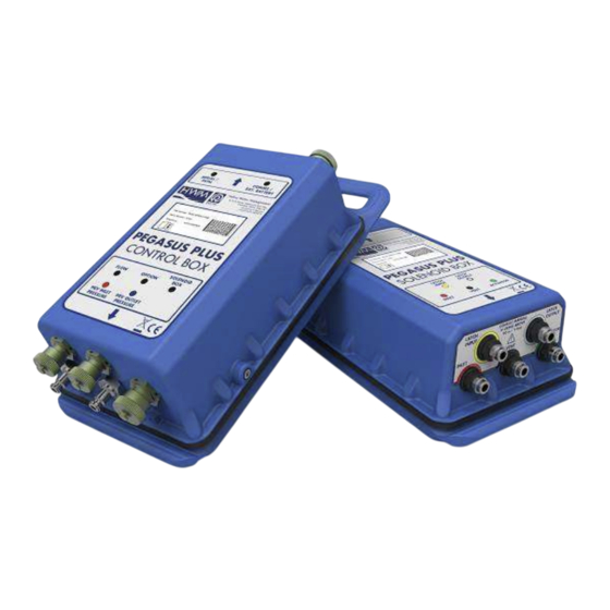
This document details the assembly and connection of the battery
and SIM card into the Pegasus + control box
Observe precautions for handling electrostatic devices at all times.
Observe any personal protective equipment requirements at all times.
Page 1 of 14
Advertisement
Table of Contents

Subscribe to Our Youtube Channel
Related Manuals for HWM Pegasus+


Summary of Contents for HWM Pegasus+
- Page 1 Assembly Procedure Pegasus+ – Battery and SIM Card Assembly in the control unit and battery assembly in the Solenoid unit This document details the assembly and connection of the battery and SIM card into the Pegasus + control box Observe precautions for handling electrostatic devices at all times. Observe any personal protective equipment requirements at all times.
-
Page 2: Important Safety Information
The equipment was produced by HWM-Water Ltd (Palmer Environmental / Radcom Technologies / Radiotech / ASL Holdings Ltd) and supplied on or after 13th August 2005 The equipment was supplied before 13th August 2005 but has been directly replaced by an HWM- Water Ltd product manufactured since 13th August 2005. - Page 3 Under HWM-Water Ltd’s Terms and Conditions of Sale, customers are responsible for the cost of returning WEEE to HWM-Water Ltd and we are responsible for the costs of recycling and reporting on that waste. Instructions for returning WEEE: Ensure that the WEEE meets one of the two conditions above.
-
Page 4: Removing The Lid
Removing the Lid 1. Remove 18 off M4 x 12 cap head screws (and retain) using a 3.0mm A/F hexagon drive bit and gently separate the lid from the case ensuring the gasket separates without damage Figure 1: A photograph illustrating the Pegasus + Control box Assembling the Battery 2. - Page 5 3. Orientate the battery so the protruding wires are located towards the handle of the lid. Assemble the battery to the lid aligning the holes on the battery with the holes on the lid (as illustrated in Figure3). Figure 3: A photograph illustrating the battery assembled with the holes of the battery and lid aligned 4.
-
Page 6: Connecting The Battery
Connecting the Battery Connect the battery lead with red heatshrink to and the other battery to of the main PCB. (as illustrated in Figure 5). Figure 5: A photograph illustrating the battery connectors mated to J20 and J14 on the PCB Installing a Sim Card 6. -
Page 7: Replacing The Lid
Figure 7: A photograph illustrating an open Sim tray (left) and an open Sim tray with a SIM inserted (right) 8. Lower the SIM card holder, and slide it in the direction indicated to lock it (as illustrated in Figure 8). Figure 8: A photograph illustrating a closed sim tray (left) and locked sim tray (right) Replacing the Lid... -
Page 8: Pressure Test
11. Replace the 18 off M4 x 12 cap head screws and tighten with a torque drive (2Nm) using a torque driver with 3mm hex bit and tightening strictly in the sequence illustrated in Figure 9. NOTE:-In order to ensure the gasket is correctly compressed it is necessary to follow the tightening sequence twice Figure 9: A photograph illustrating the 18 off screws securing the lid and the sequence in which they must be tightened. - Page 9 14. Insert the test adaptor and pressurise to 0.7bar (10psi) for 1 minute and observe for any internal pressure drop (as illustrated in Figure 12). Figure 12: A photograph illustrating the test adaptor and a pressure gauge 15. After a successful test, replace the M4 x 16 seal screw and tighten to 2 Nm using a torque driver with an appropriate bit (as illustrated in Figure 13).
- Page 10 Solenoid box battery pack assembly 17. As per the control box remove the 18 screws which secure the lid, remove the lid and the gasket. Check the lid has foam tape in the position indicated below:- 18. Place the battery onto the lid so the handle is on the left and the wire from the battery is at the bottom.
- Page 11 19. Apply 6 screws each fitted with a washer to secure the battery pack to the lid in the location and orientation shown. Tighten the screws with a torque driver (1Nm). 20. Apply a gasket to the housing so the smooth face is facing upwards. 21.
- Page 12 22. Place the lid next to the housing as shown. Connect the battery to the extension lead from the PCB. Use a double sided sticky pad to secure the battery wire in place as shown. 23. Connect the 2 way connector to the battery extension cable. CARE POINT: Ensure when mating the cables that the same coloured wire is connected together (RED to RED and BLACK to BLACK).
- Page 13 Pressure Test 25. Remove the Void label (as illustrated in Figure 10). Figure 15: A photograph illustrating the void label that requires removal 26. Remove (and retain) the M4 x 16 seal screw (as illustrated in Figure 11) using an appropriate bit.(alternative screw heads may be used) Figure 16: A photograph illustrating the pressure screw that needs to be removed and retained 27.
- Page 14 MAN-125-0005-A [Pegasus+ Sim and battery assembly] ©HWM-Water Limited. This document is the property of HWM-Water Ltd. and must not be copied or disclosed to a third party without the permission of the company. Copyright reserved. Page 14 of 14...
Need help?
Do you have a question about the Pegasus+ and is the answer not in the manual?
Questions and answers